
A collection of helpful guides for activities related to the training series.
Table of Contents
Check The COM Port In Windows Device Manager
To check what COM port is connected to Arduino, you can check in the Device Manager.
From the Start menu, begin typing “device manager” in the search field. When the Device Manager icon appears, click to open.

Expand the heading labelled Ports (COM & LPT) to view connected COM ports. The microcontroller board will be visible only when it is connect via USB cable.

Check Properties On Your PC
To determine if a 32 bit or 64 bit version of Windows on your PC, you can check from the File Explorer by right clicking on This PC and then select Properties. A dialog box with device specifications will appear. Other PC properties are displayed including the device name.


Check What Version Of CODESYS Control Win Soft PLC Is Installed
If you don’t recall if the 32 bit or 64 bit version was installed you can check by clicking the “ ^ ” symbol on the taskbar.
Right click the icon for the soft PLC and then click on About

The version is displayed

Start Or Stop CODESYS Control Win Soft PLC And Gateway
The soft PLC and gateway must both be running to work online with the soft PLC. You can see the status of by clicking the “ ^ ” symbol on the taskbar to show hidden icons.
If the services are not running, then the icon will appear greyed out.

You can access control to start / stop the services by right clicking the icon.

Slave Device Communication Troubleshooting
If the slave device communication is not working, try the following:
Step 1
With the application running, from the Online menu select Reset Warm. After the reset the application will be stopped. Click the Play button to restart the application. Check for the green circular arrows in the devices view, that indicate slave device communication status. Or check for blinking yellow TX and RX LEDs on the board. Still not working? Move on to step 2.

Step 2
From the Online menu select Multiple Download to reload the project. You will be prompted with a dialog box.
Select Always perform a full download and release any forced variables
Make sure there is no checkmark for Start all applications after download or online change
Then click OK to download.

After the download the application will be stopped. Click the Play button to restart the application.

Check for the green circular arrows in the devices view, that indicate slave device communication status. Or check for blinking yellow TX and RX LEDs on the board. Still not working? Move on to step 3.
Step 3
From the Online menu select Logout. Return to the section Add Slave Device Configuration To Project and check parameters. Confirm the correct COM port is selected. To check what COM port is connected to the slave device, see Appendix section Check The COM Port In Windows Device Manager. Also check baud rate and parity. For Channels 0 to 3 check access types, offsets and lengths. Be aware that the offsets will be displayed in hex. #16 0000 and 0X0000 are OK. If you find errors, correct them then login to the online PLC again. You will be prompted to download, select yes. Start the application again.
Check for the green circular arrows in the devices view, that indicate slave device communication status. Or check for blinking yellow TX and RX LEDs on the board. Still not working? repeat the warm reset procedure from step 1.
Step 4
Save the project then close the CODESYS session and stop the Soft PLC. Return to the section for the microcontroller board Modify Sketch and Upload to Microcontroller Board. Confirm that the sketch is correct and the ID changed from 0 to 1. Re-upload the sketch if necessary. Then re-open the CODESYS project, Start the soft PLC and repeat section Connecting To PLC Online.
Check for the green circular arrows in the devices view, that indicate slave device communication status. Or check for blinking yellow TX and RX LEDs on the board. Still not working? repeat the warm reset procedure from step 1.
Communication Settings Connection Path To PLC
When a new CODESYS project is created, or working with a fresh install of the soft PLC, steps need to be taken to define the connection path to the PLC and setup the PLC login.
To work online with the soft PLC, both the gateway and PLC must both be running. To see how to check the status and start / stop the services, check in the Help Section. The guide is titled Start Or Stop CODESYS Control Win Soft PLC And Gateway.
To proceed, open the desired CODESYS project. Double click the Device object to open the editor. The Communication Settings tab should be selected. A graphic image of the PLC network is displayed. The image shows icons for the PC to the left, the gateway to the middle and the PLC to the right. The gateway and the PLC icons both have a round dot status indicator at the lower right. When the dot is green it means the device is connected.
To define the connection path, select the Scan Network tab at the top of the window.

The scan will detect any devices connected to the gateway. A dialog box titled Select Device will appear, showing devices found under the gateway heading. The soft PLC should appear here. Since it is installed on your PC, the name will match device name of your PC. If you unsure what the device name is for your PC, see the guide Check Properties On Your PC in the Help Section.
Select the desired device and then click OK to accept the change.

To Create Password
If this is a fresh in install of the soft PLC you must set up user management and create a password. Otherwise skip to Device User Logon below.
A message will appear asking if you wish to activate user management. This will prompt you to create an administrator account to access the PLC. You must select Yes to proceed.

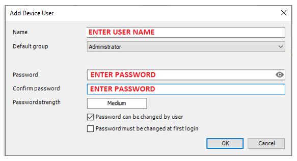
The add device user dialog box will appear. Enter a user name and password to for the new account. Remember the user name and password to access the PLC in the future. Click OK to create the account.
Device User Logon
Next you will be prompted to provide a user name and password to connect to the PLC. Enter the user name and password from the account you just created. Then click OK

The image of the PLC network should show green status for both the gateway and the PLC.
