This section is all about how to setup a PLC trainer with CODESYS and Arduino.
Table of Contents
Overview

The intent of this documentation is to provide instructions to set up a PLC training station that can be used to practice PLC programming. When we learn the basics of PLCs, we discover 3 main components are the CPU (or processor), Inputs and Outputs (I/O). So, it stands to reason that an effective PLC training station should have these things. The setup described here is intended to meet these requirements using a Soft PLC application installed on a PC as the processor and an inexpensive microcontroller board for I/O. A PLC project is created with the required communication configuration and saved as a base project. The base project can serve as a starting point for each exercise or lab. With that base in place, simply open a copy of the base project, and then focus on learning programming instead of repeating the communication setup.
Items required for the PLC training station:
- A PC to run the software for development and soft PLC. For this example, we are using a Windows 10 laptop.
- Arduino Uno R3 microcontroller board (or compatible) to connect our PLC to inputs and outputs.
- USB cable USB-A to USB-B to connect the PC to the Arduino board
- A Breadboard (830 tie points) with jumper wires to wire up the Arduino board.
- Resistors – 5 X 10 Kohm and 5 X 220 ohm
- LEDs – 1 each red, yellow, green, blue and white
- Push Button Switches – 5 X Normally Open (NO), Gikfun Part # EK1019 or similar
- Potentiometer – 1 X 10 Kohm, Pier Part # PT15NV02-103A2020-S or similar
CODESYS Control Win
A soft PLC is software you can run on a computer that will function as a PLC processor. The benefit of the soft PLC, when learning, is that you can practice the development of PLC applications without purchasing expensive and specialized hardware.
The soft PLC software selected for this training station is CODESYS Control Win. CODESYS is a provider of manufacturer-independent automation software, so it is not limited to PLCs provided by a single manufacturer. It is used by multiple PLC vendors. Festo, Eaton, ABB and Turk are just a few of the vendors with CODESYS compatible PLCs. The soft PLC can be programmed with software titled CODESYS Development System. The soft PLC and the development system both conform to IEC 61131-3. That is the industry standard for PLC programming languages. That means the training station will be suitable for practicing any standard PLC language, such as ladder diagram.
In demo mode, the soft PLC runs for 2-hour intervals, with full features, without a license. After the 2-hour limit the soft PLC must be restarted.
The CODESYS Development System can be downloaded from the CODESYS website. The soft PLC, CODESYS Control Win, is included with the bundle that is downloaded with the development system.
You can learn more about CODESYS by visiting the website. https://www.codesys.com/
Arduino UNO
The Arduino UNO board is a microcontroller board, designed for learning electronics, developed by Arduino.cc. The board has built in inputs and outputs (I/O). There are 14 pins for digital I/O that can be assigned as input or output. There is an analog to digital convertor that provide 6 analog inputs with 10 bit resolution.
The board can generate analog output signals using Pulse Width Modulation (PWM). PWM is a method of controlling a digital output’s frequency and duty cycle to deliver the desired average voltage. PLCs normally rely on digital to analog converters for analog outputs, but the PWM method is suitable for our training station.
The board is programmable with software titled Arduino Integrated Development Environment (Arduino IDE). When programmed to do so, the Arduino Uno can communicate, as a slave device, with the soft PLC and connect it to real word inputs and outputs. This makes it ideal for our training station.
The version selected for our training station is Arduino UNO Rev3.
You can learn more about Arduino by visiting the website. https://www.arduino.cc/

Install CODESYS On Your PC
If the CODESYS soft PLC and development system are not already installed on your PC you will have to download from the CODESYS website. It will be required to select between a 32 bit or 64 bit version. The 64 bit version is not suitable for a 32 bit PC. You will need to know ahead of time, what type of OS is on your PC. If you need to know how to check what version is installed, see Check Properties On Your PC in the Help Section.
Download
Software is available from the CODESYS Store website.
In Canada, USA and Mexico go to https://us.store.CODESYS.com/
Everywhere else, go to https://store.CODESYS.com/de/
An account is required and must be signed in to download. From the CODESYS Store website. Click on Sign In at the upper right of the screen. This will take you to the customer login screen.

From the customer login screen, you have options:

Once registered and signed in you will return to the CODESYS Store page. From here you can select to download the 32 bit or 64 bit version.

When you select a version to download, the licence agreement will appear. After reading the agreement, you must accept the terms to continue with the download. The download location will vary depending on your browser and your chosen setup.
Install
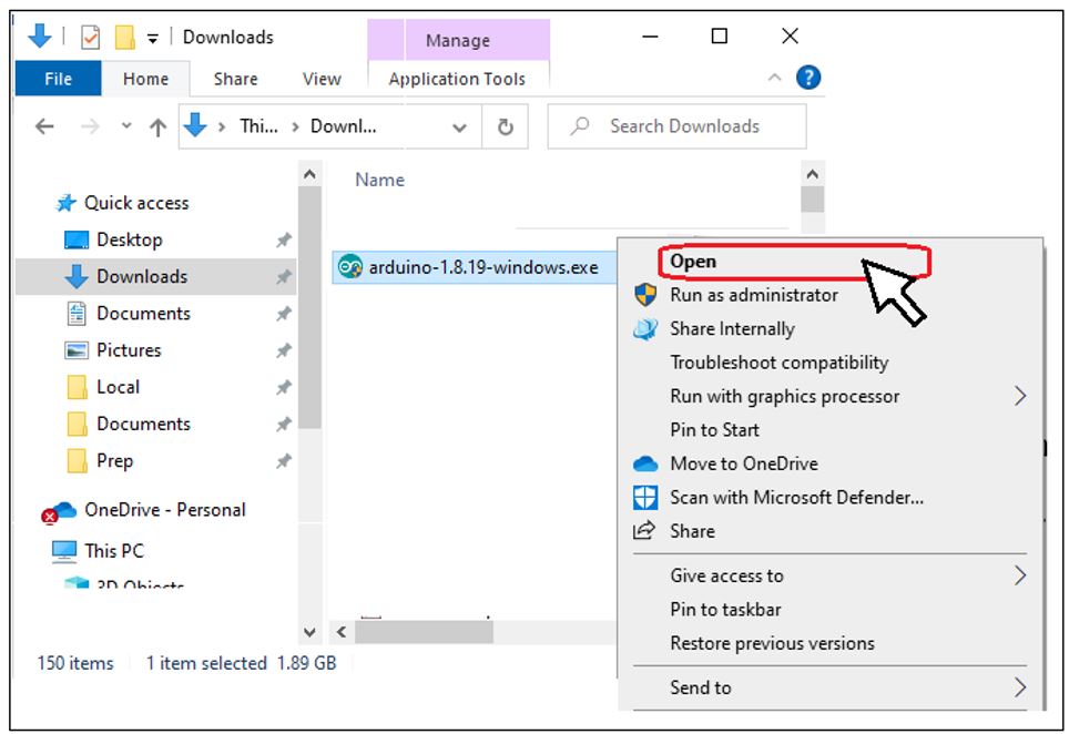
From the file’s download location or wherever you chose to move it, open the file to start the installation. Alternately you can double-click it or, if you are not logged in to an administrator account, you may have to select Run as administrator. Follow the prompts to continue the installation.

When you are prompted to select the setup type, select Complete. This installs the full bundle including the CODESYS Control Win soft PLC.

Continue following the prompts to complete the installation. At that point, the necessary CODESYS software will have been installed on your PC.
Arduino Board Software
Download and Install Arduino IDE On Your PC
Download
Software is available from the Arduino website.
Got to https://www.arduino.cc/en/software
Select the Windows version of the IDE to download.

The download location will vary depending on your browser and your chosen setup
Install
From the file’s download location or wherever you chose to move it, open the file to start the installation. Alternately you can double-click it or, if you are not logged in to an administrator account, you may have to select Run as administrator. Follow the prompts to continue the installation.
When prompted to select components to install, it is recommended to install all components. The shortcuts and are optional, but useful.
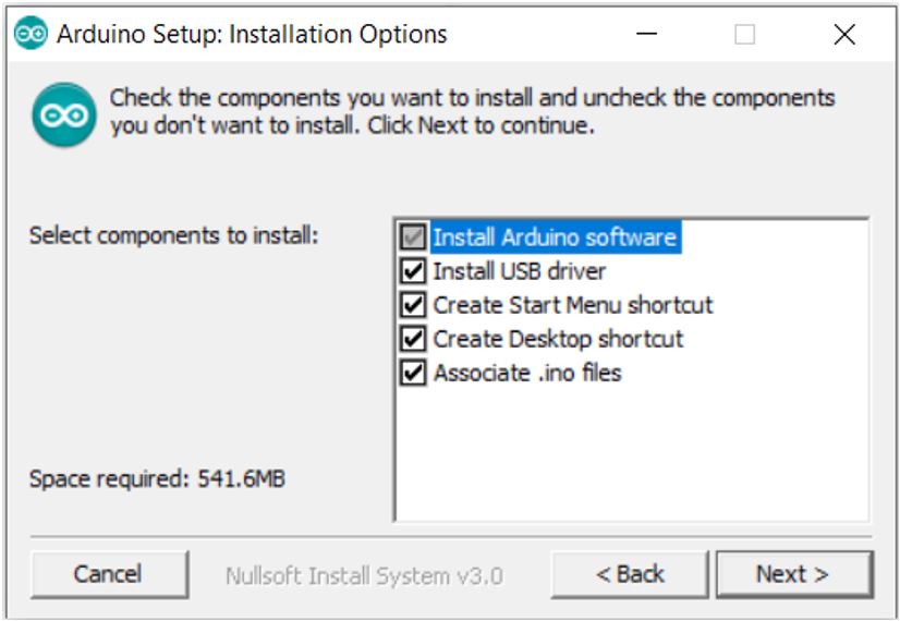
Continue following the prompts to complete the installation.
Open And Setup Arduino IDE
Start the Arduino IDE on your PC:
| by double clicking the icon | Or selecting from start menu 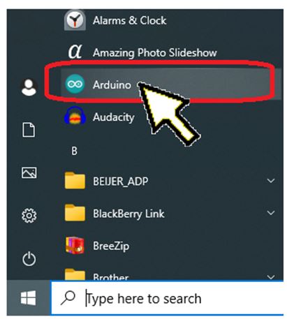 |
The Arduino IDE window will appear. From the Tools menu, select the board type Arduino Uno.

Connect the microcontroller board to the PC with a USB cable. Set the COM port from the Tools menu. The COM port should match the port assigned in the Windows Device Manager. If you need to know how to check the COM port, see the guide Check The COM Port In Windows Device Manager in the Help Section.
If the board is not connected to the PC it will not be visible from the Tools menu or the Device Manager.

The board type and COM port are displayed at the lower right of the window.

Acquire The Slave Device Sketch and Load It To The Arduino Board
The microcontroller board can be programed to perform many different tasks. Programs for Arduino are called “sketches”. A sketch to set up the microcontroller board, as a slave device, already exists. It was designed and developed to work with OpenPLC devices. Open PLC is a fully open-source Programmable Logic Controller. The OpenPLC project is another great way to learn about PLCs.
You can learn more about OpenPLC from their website. https://www.openplcproject.com/
The sketch for the OpenPLC slave device, with a small adjustment, works just as well with the soft PLC, for our training station. The connection between the Soft PLC and the slave device uses a communication protocol called Modbus. It is the Modbus slave ID number that we will adjust in the sketch.
When the sketch has been loaded to the board, it will become a slave device. The I/O pinout is shown in the diagram titled Slave Device I/O. Pins 2, 3, 4, 5 and 6 will be digital inputs. Pins 7,8, 12 and 13 will be digital outputs. Pins 9, 10 and 11 serve as analog outputs. Pins A0 through A5 are analog inputs.

Download The Sketch
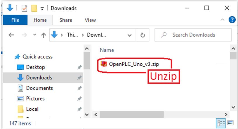
Click the link to download a copy of the sketch, modified for our training station, here.
The download location will vary depending on your browser and your chosen setup. . From the file’s download location or wherever you chose to move it, Unzip / Extract it to prepare for use.
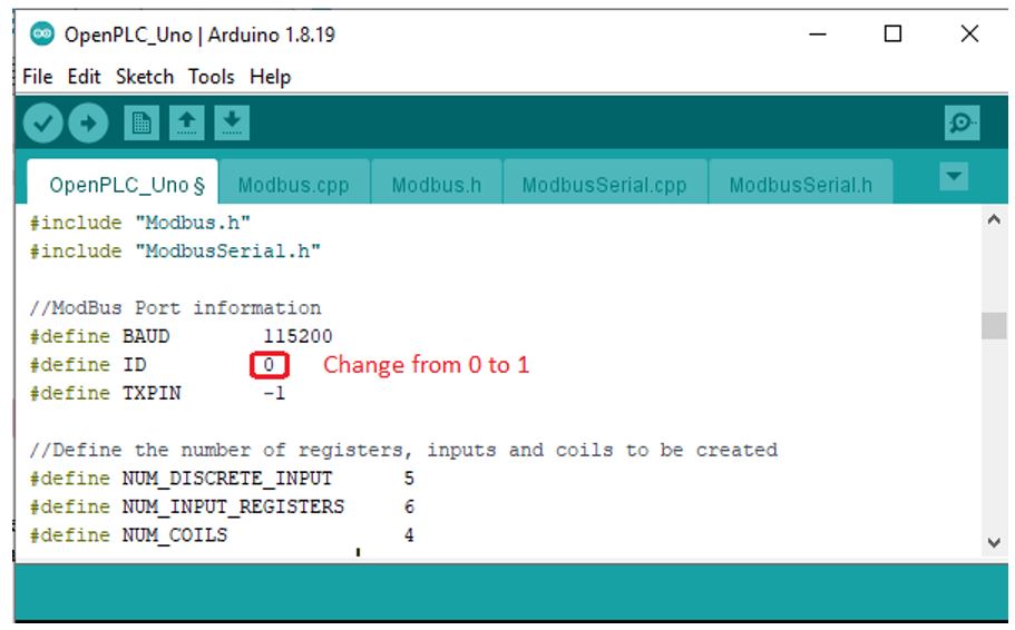
How was the Sketch Modified?
“//ModBus Port information” changed the ID from 0 to 1. This is the Modbus address for the slave device.
Upload to Microcontroller Board
From the extracted folder “OpenPLC_Uno_v3” find the file “OpenPLC_UnoCodesys.zip”. Double click to open the sketch with Arduino IDE.

The window for the Arduino IDE will appear.
Make sure the board is connected to the PC with USB cable and the correct board type and COM port are selected. Transferring the file to the microcontroller board is referred to as Uploading by the Arduino IDE. From the Sketch menu select Upload.

While in process, a message is displayed that will say “Compiling Sketch” or “Uploading”.

When the transfer is complete. The message “Done Uploading” will appear.

At this point, you have completed the software tasks for the microcontroller board.
Wiring The Arduino Board
The diagram titled Microcontroller Schematic shows how the training stand will be connected to real world I/O through the slave device.
The digital inputs at pins 2, 3, 4, 5, and 6 are wired as sinking inputs. Each digital input has a NO push button that will switch on +5 volts when pressed. Each input also has a 10 Kohm, pull-down, resistor connected. This ensures that inputs go to 0 volts when the buttons are released. The microcontroller board inputs are sensitive to noise and false ON signals happen frequently without the pull-down resistors in place.
The digital outputs at pins 7, 8, 12 and 13 are wired as sourcing outputs. Every digital output has a coloured LED, Red, Yellow, Green or Blue that will light up when the output is on. There are 220 ohm, current limiting, resistors in series with each LED.
An analog output, at pin 9, is connected to a white LED with a current limiting resistor in series. The wiring is similar to the digital outputs. What is different is that the analog output will use PWM to control the brightness of the LED rather than just turning it on and off.
An analog input, A0, is connected to the wiper of a 10 Kohm potentiometer. Based on it’s adjustment, the potentiometer can provide a voltage of 0 VDC to +5 VDC.
A proposed plan for the breadboard is shown in the diagram titled Suggested Board Layout. To the left shows a breadboard with the basic components in place. To the right is the breadboard with wiring completed, with the microcontroller board and the wire jumpers in place. Of course, you may chose to wire the breadboard in your own way.


Setup The Soft PLC For Slave Device
Create New Project
Start the CODESYS Development System:
| by double clicking the icon | Or selecting from start menu |
Select New Project from the Start Page.

From the New Project dialog box, select Standard Project. This project will be our Base project that we will use for our training station. So, a good name would be “Training Station Base”
Once the selections have been made, click OK.

Select the CODESYS Control Win Soft PLC as the device. Think back to when we installed the CODESYS software. Did you install the 32 bit or 64 bit version. You need to select the device accordingly. If you need to know how to check what version is installed, see the guide Check What Version Of CODESYS Control Win Soft PLC Is Installed in the Help Section.
Our purpose for setting up the training station is to learn ladder logic. So, select Ladder Logic Diagram for PLC_PRG.
Once the selections have been made, click OK. The new project will be created.


Add Slave Device Modbus Config To Project
Right click the Device object and select Add Device.

The Add Device dialog box will appear. Under the heading Modbus, double click Modbus COM to add the device. Then click on the X symbol at the upper right of the Add Device dialog box to close.

Double click the Modbus_COM object to open the object editor. Select the General tab to set the baud rate to 115200 and the parity to NONE. The COM port parameter should match the port assigned to the microcontroller board. If you do not recall the port number, you can check the device manager. The method to check the device manger in the Help Section, titled Check The COM Port In Windows Device Manager.

Right click the Modbus_COM object and select Add Device.

Under the heading Modbus Serial Master double click Modbus Master, Com Port to add the device. Then click on the X symbol at the upper right of the Add Device dialog box to close.

Right click the Modbus_Master_COM_Port object and select Add Device.

Under the heading Modbus Serial Slave double click Modbus Slave, Com Port to add the device. Then click on the X symbol at the upper right of the Add Device dialog box to close.

Double click the Modbus_Slave_COM object to open the object editor. Select the Modbus Slave Channel and then select Add Channel to set up Channel 0.

Set the Parameters for Channel 0 as shown below. Then click OK to accept changes.

Select Add Channel to set up Channel 1.

Set the Parameters for Channel 1 as shown below. Then click OK to accept changes.

Select Add Channel to set up Channel 2.
Set the Parameters for Channel 2 as shown below. Then click OK to accept changes.

Select Add Channel to set up Channel 3.
Set the Parameters for Channel 3 as shown below. Then click OK to accept changes.

At this point the slave device configuration is completed. It is a good time to save the project.
Testing The PLC Training Station
Communication Settings Connection Path To PLC
Since this is the first time connecting with a new project, on a fresh install of the soft PLC, steps need to be taken to define the connection path to the PLC and setup the PLC login.
To work online with the soft PLC, both the gateway and PLC must both be running. To see how to check the status and start / stop the services, check in the Help Section. The guide is titled Start Or Stop CODESYS Control Win Soft PLC And Gateway.
To proceed, open the project for the training station. Double click the Device object to open the editor. The Communication Settings tab should be selected. A graphic image of the PLC network is displayed. The image shows icons for the PC to the left, the gateway to the middle and the PLC to the right. The gateway and the PLC icons both have a round dot status indicator at the lower right. When the dot is green it means the device is connected.
To define the connection path, select the Scan Network tab at the top of the window.

The scan will detect any devices connected to the gateway. A dialog box titled Select Device will appear, showing devices found under the gateway heading. The soft PLC should appear here. Since it is installed on your PC, the name will match device name of your PC. If you unsure what the device name is for your PC, see the guide Check Properties On Your PC in the Help Section.
Select the desired device and then click OK to accept the change.

A message will appear asking if you wish to activate user management. This will prompt you to create an administrator account to access the PLC. You must select Yes to proceed.

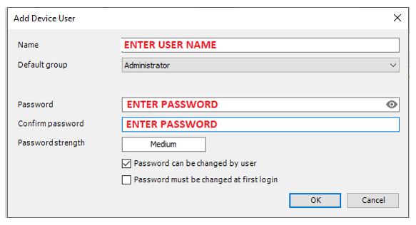
The add device user dialog box will appear. Enter a user name and password to for the new account. Remember the user name and password to access the PLC in the future. Click OK to create the account.
Next you will be prompted to provide a user name and password to connect to the PLC. Enter the user name and password from the account you just created. Then click OK

The image of the PLC network should show green status for both the gateway and the PLC.

Connecting To PLC Online And Download
Before going online, make sure the slave device (microcontroller board) is connected to the PC with a USB cable.
Connecting or disconnecting the CODESYS Development System and PLC is accomplished by the Login and Logout commands, available from the Online menu. To work online with the PLC, select the Login command.

Since there is no application loaded to the PLC, you will be prompted to transfer to the PLC. Transferring files to the PLC is referred to as Downloading. Select Yes to download the application to the PLC.

The device and application objects will be highlighted in green, indicating the PLC is online. In parenthesis the device indicates it is connected, the application indicates it is stopped.

Starting The Application And Testing Modbus
Starting and stopping the application is accomplished with the Start and Stop commands available from the Debug menu. To start the application, select the Start command.

Green arrows that form a circle, are indicators that the slave device communication is working. Blinking yellow TX and RX LEDs on the board, indicate communication is working on that end as well. If communication is not working at this point, see the guide Slave Device Communication Troubleshooting in the Help Section.

If communication between the slave device and PLC are working, it is a good time to save your project. To prepare for the next step, stop the application and logout to disconnect from the PLC.
I/O Test
It is important to test the real world I/O connected to the training station. It can really complicate our efforts to learn programming if the hardware is not working. When you continue the learning series, Exercises 4 through 9 will take you step by step through the process of writing a Ladder program designed to test the digital I/O. Then describe how to perform the test. Later in the series there will be a test for the analog I/O. So, if you want to wait until then that is OK and you can consider the training station setup complete for now. But, if you are eager to see this thing in action, then complete these last few steps.
We will create a separate project with programing to put the inputs and outputs through a test run. The code for the program is provided. It is in Structured Text (ST) format to make it easy to cut and paste. The test is a simple one, as each of the push buttons is pressed an assigned LED, red, yellow, green or blue should light. Then, when the potentiometer, connected to an analog input, is adjusted it should control the brightness of the white LED.
Create Test Project
We will create the new project for this exercise using a copy of the base project that was already setup. This way the new project already has the communication config for the slave device.
Make sure you have saved the project “Training Station Base”.
With the project “Training Station Base” open, from the File menu select Save Project As.
Save with new name “IO Test” to create the test project.

To create a new program for the test logic, right click the Application object, select Add Object and then select POU.

The name for the new POU will be IO_Test. It will be a program type and the language will be structured text. Select Add to create the new program.

The new program IO_Test should appear in the window to the left. The editor for the program should be open and visible in the middle of the screen with the program name in the tab above. If the editor is not open, double click the object for the program IO_Test to open the editor.

The text is the rectangle below is the code, in structured text format, that is to be copied to the program IO_Test. This is not intended to be a lesson on structured text. Using the ST language is simply the easiest way to copy text from this document into our test program.
| //Start Here // IO Test Program for training station // Cut and Paste to Structured Text POU // PB 1 @ input0(Pin2) and PB5 @ input4(Pin6) light Red LED @ output0(Pin7) %QX0.0 := %IX0.0 OR %IX0.4; // PB 2 @ input1(Pin3) light Yellow LED @ output1(Pin8) %QX0.1 := %IX0.1; // PB 3 @ input2(Pin4) light Green LED @ output2(Pin12) %QX0.2 := %IX0.2; // PB 4 @ input3(Pin5) light blue LED @ output3(Pin13) %QX0.3 := %IX0.3; // Pot @ A0 controls brightness of white LED @ Pin9 %QW1 := %IW1; //End Here |
Place the mouse cursor at the beginning of the blue text (//Start Here), click to select and highlight until the end of the blue text (//End Here) and copy. Then paste to the editor for IO_Test

The code should appear in the editor window.

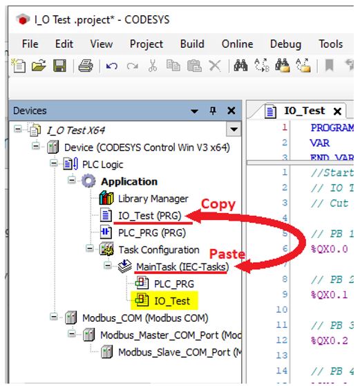
A quick and easy way to set up the program to execute as part of the main task is to copy the program from under the heading Application and paste to the heading MainTask.
When the program IO_Test is included under the heading MainTask it is time to save the project.
Connect And Download Test Project
Before going online, make sure the slave device (microcontroller board) is connected to the PC with a USB cable.
Make sure the soft PLC and gateway are running. (see Start Or Stop CODESYS Control Win Soft PLC And Gateway in the Help Section)
With the project “IO_Test” opened, use the Login command to connect to the PLC. Enter the username and password if prompted. When prompted to download the application, select Yes.
Use the Start command to start the application. Then, determine modbus communication is OK by checking the RX / TX LEDs on the slave device or the circular green arrows beside the modbus objects in the left hand window. If communication is not working at this point, see the guide Slave Device Communication Troubleshooting in the Help Section.
Connected and running, it should look like this:

I/O Checklist
To test the inputs and outputs, use the I/O checklist below. Press each of the buttons and adjust the potentiometer. Check for the appropriate output action. If the input and output actions match the list, put a check mark in the row for the input / output pair.

At this point you have completed the PLC training stand setup and testing. You are ready to advance to learning PLC programming.