Numeric Data Types in PLC Programming

See The Video Here

When working with programmable logic controllers (PLCs), understanding numeric data types is essential. PLCs rely on various data types to handle information effectively, from simple Boolean states to complex floating-point calculations. This blog explores the building blocks of data units, the key numeric data types, and their practical applications in PLC programming.


Sizing of Data Units

At its core, digital information in a PLC is made up of bits. These bits can be grouped into larger units depending on their function. Here’s an overview:

  • Bit: The smallest unit, representing either 1 (on) or 0 (off).
  • Nibble: A group of 4 bits.
  • Byte: Composed of 8 bits.
  • Word: Composed of 16 bits.
  • Double Word: Composed of 32 bits.

These units form the foundation for all data types used in PLC programming.


Basic Data Types

The basic (or atomic) data types represent fundamental pieces of information. They include:

1. Boolean

  • Size: 1 bit.
  • Purpose: Represents two states, 1 (true/on) or 0 (false/off).
  • Example Use: Detecting whether a sensor is activated.

2. Unsigned Integers

Unsigned integers represent positive whole numbers.

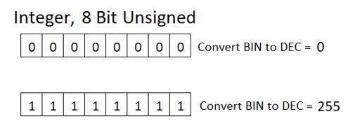
8-Bit Unsigned Integer:

  • Size: 1 byte (8 bits).
  • Range: 0 to 255.

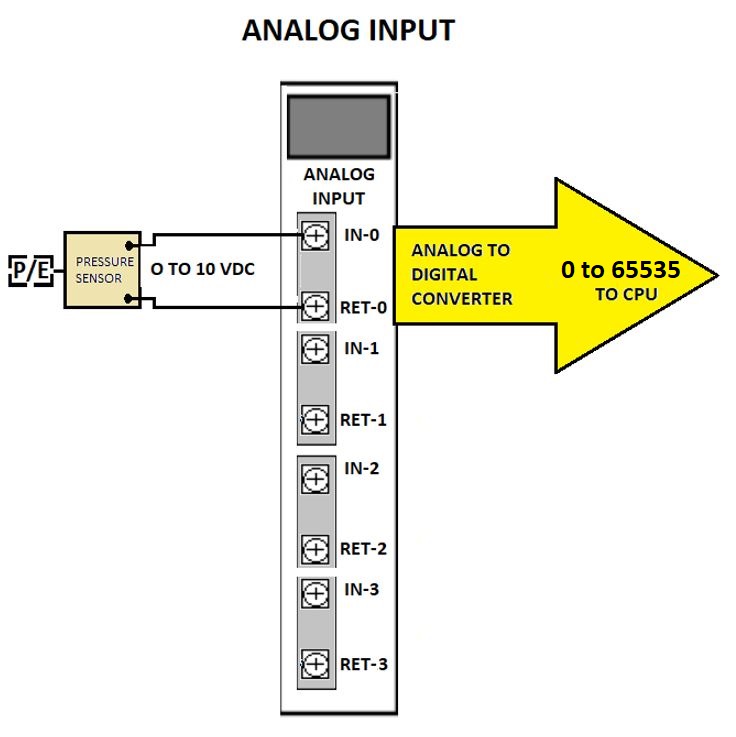
16-Bit Unsigned Integer:

  • Size: 1 word (16 bits).
    • Range: 0 to 65,535.

3. Signed Integers

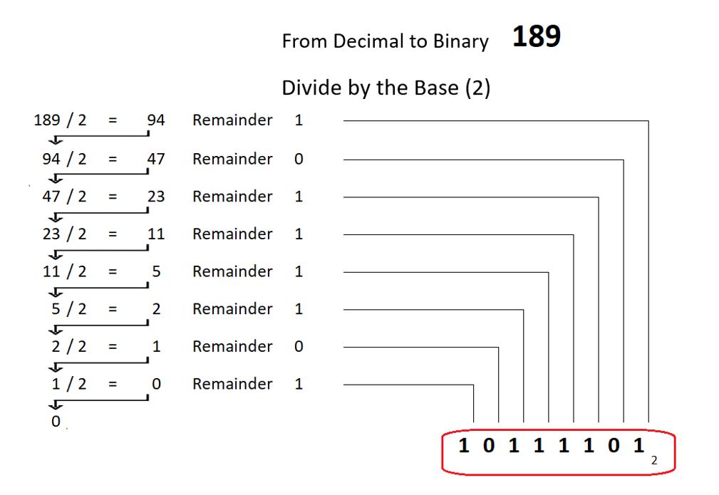
Signed integers handle both positive and negative whole numbers. When converting signed integers from binary, there is a special arrangement to handle negative as well as positive values. The bit that is most to the left is considered the most significant bit (MSB). The signed integer data type uses the MSB for a special purpose. The MSB is assigned a negative value if that particular bit is set to 1. This gives the format the capability to express negative numbers.

8-Bit Signed Integer:

  • Size: 1 byte (8 bits).
  • Range: -128 to 127.

16-Bit Signed Integer:

  • Size: 1 word (16 bits).
    • Range: -32,768 to 32,767.
    • The most significant bit (MSB) determines the sign. If the MSB is 1, the number is negative.

32-Bit Signed Integer:

  • Size: 1 double word (32 bits).
  • Range: -2,147,483,648 to 2,147,483,647.

Floating Point

See The Video Here

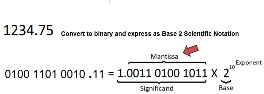
Floating-point data types store numbers with decimal places. Consider the Single Precision Floating Point as an example. It occupies a Double Word (32 bits). The way that data is encoded within the 32 bits is very different then what we see with integers. To manage a wide range of numbers with decimal places, the 32 bit structure is divided into 3 subgroups. The subgroups hold different attributes that encode a value. The following is a brief description of the structure of the data type.

1 bit will represent the sign of the number, 0 if positive and 1 if negative.

8 bits are assigned to the purpose of storing an exponent value. An exponent is a component of a number when it is expressed in scientific notation. In this case it is a form of scientific notation that is at Base 2 .

23 bits are assigned to hold compressed details of the number that is known as the Mantissa. The Mantissa is also a component of a number when it is expressed in this Base 2 version of scientific notation.

Single Precision Floating Point

  • Size 1 double word ( 32 bits ).
    • 1 bit: Sign (0 = positive, 1 = negative).
    • 8 bits: Exponent.
    • 23 bits: Mantissa.

Floating points are ideal for applications requiring precision, such as temperature or flow rate measurements.


Other Data Types

Structured Data Types

Combinations of the basic, atomic, data types can be grouped together and they are called structures. PLCs utilize these structured data types to handle specific tasks. There are predefined structured data types for timers, counters and file control operations just to name a few.

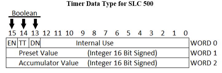
Consider a Timer Data Type for an Allen Bradley SLC 500 PLC. It is made up of three 16 bit words. Bits 13, 14 and 15 of Word 0 are boolean data type. The booleans are to express the on/off state for the timer Enable, Timer-Timing and Done. Word 1 and Word 2 are signed 16 bit integers containing numeric data for the timer preset and accumulator.

User-Defined Data Types (UDTs)

Some PLCs allow custom structures, enabling programmers to define data types tailored to their application by combining existing ones.


Conclusion

Numeric data types are the backbone of PLC programming, enabling the efficient handling of data for a wide range of applications. Whether you’re toggling a simple boolean state or performing precise floating-point calculations, selecting the right data type ensures your system operates smoothly.

Take time to understand your PLC’s predefined options, and don’t hesitate to explore user-defined types for custom applications. Proper data management is a cornerstone of robust PLC programming.

Coming Soon – More PLC Blogs


Understanding Numbering Systems in PLCs

See The Video Here

Why Numbering Systems Matter

When it comes to working with PLCs, numbering systems are fundamental, whether you’re just diving in or have years of experience. Knowing the different numbering systems and data types helps in programming, troubleshooting, and working effectively with PLCs and industrial control systems.

At the heart of every PLC and computer system is digital code—often summarized as “ones and zeros.” This is the binary system, an example of a numbering system made up of just two digits: 1 and 0. Each of these binary digits, or bits, represents one unit of PLC memory and can be either on (1) or off (0). When bits are grouped together, they can represent values beyond a single on/off state, forming the basis of complex data handling in PLCs.

Where You’ll Encounter Numbering Systems in PLCs

Here are some examples:

  • Binary: Used internally by PLCs to process data at the most basic level.
  • Decimal: Often used in operator interfaces, where data is displayed in a human-friendly format.
  • Octal: Used by some PLCs, especially older ones, for addressing memory locations.
  • Hexadecimal: Commonly used for error codes.

Each numbering system has its own purpose and advantages, which we’ll explore below.


Positional Numbering Systems

Numbers, as we understand them, appear before us as a row of symbols called digits. The value of a digit depends on its position in the row with least significant to the right and most significant to the left.

Each numbering system has a base (sometimes called radix) The base is the quantity of unique digits, including the digit zero, used to represent numbers in a positional numbering system. We can break this down using an example. We can consider the decimal system since it is most familiar to us. There are 10 unique digits, 0 through 9. So, we can say the decimal system has a base of 10. If we are counting up beyond the digit 9, a one is carried over and added to the position to the left.

A common way of expressing the base is a small number to the lower right, in subscript.

The relationship between a digit, its position and the base of the number can be expressed as:

This equation determines the place value. For example, the position value for each digit in the decimal number 2022 can be calculated:

Add the place values together and you will find the overall value of the number.

Decimal System (Base 10)

We have already talked about the decimal system in the previous example. These are ordinary everyday numbers for most of us. The digits in this system are 0, 1, 2, 3, 4, 5, 6, 7, 8, 9. Let’s summarize the decimal system with one more image of the decimal number 2022.

Binary System (Base 2)

The binary system is essential for PLCs and digital systems. The digits in this system are 0 and 1, representing an off or on state.

To convert from decimal to binary, divide the decimal value by 2. Make note of the quotient and jot down the remainder as the least significant digit of the converted number.

Now take the quotient from the previous division and divide it by 2. Make note of this result and jot down the remainder as the next most significant digit of the converted number.

Octal System (Base 8)

The octal system is based on eight unique digits (0–7). Older PLCs sometimes use octal numbering for addresses.

Converting from decimal to octal follows a similar method as binary: divide the decimal by 8, noting each remainder, until the quotient reaches zero.

Hexadecimal System (Base 16)

The hexadecimal system has 16 digits: 0, 1, 2, 3, 4, 5, 6, 7, 8, 9, A, B, C, D, E, F. It is often seen in error codes and addresses.

To convert a decimal to hexadecimal, divide by 16. If the remainder exceeds 9, substitute with the corresponding letter (A for 10, B for 11, etc.).

The Practical Side of Number Conversion

See The Video Here

You can manually convert numbers between bases using the steps outlined, but for quick conversions, most engineers use tools like the Windows Calculator in Programmer Mode. This mode allows switching between decimal, binary, octal, and hexadecimal, saving time and reducing errors. This is the easy way.

Binary Coded Decimal

Binary Coded Decimal (BCD) is different from the numbering systems we have looked at so far. It is not a positional numbering system. BCD is designed to interact with field devices, known as thumb switches and 7-segment displays, to input and display decimal numbers using a binary code. Each decimal digit is stored as a separate 4-bit group, called a nibble.

Here’s how BCD encodes 0–9 in 4-bit binary:

For example, the decimal number 5092 would be represented as 4 nibbles: 0101 0000 1001 0010


Wrap-Up

Each numbering system has a role to play in PLC programming and control systems, from internal binary data handling to hexadecimal error codes. Understanding these systems and how to work between them makes you a more effective programmer, helping bridge the gap between the PLC’s digital world and human-readable formats

If you enjoy reading these blogs about PLC basics , then you might want to check out this course on Udemy called the Pre PLC Programming Course. The information here is based on material from that course. It is not geared toward any particular brand of PLC our programming software. The fundamentals are relevant to all types of PLCs. Or, take a look at other courses offered here.

Up Next – Numeric Data Types in PLC Programming


PLC Basics: Analog I/O in PLCs, Bridging the Digital and Real Worlds

See The Video Here

Previously we discussed discrete inputs and outputs and how those I/O signals are either “on” or “off”. But what about signals that continuously vary, like temperature, pressure, or speed? That’s where analog I/O comes in. Analog inputs and outputs allow PLCs to read and control continuously variable signals, opening up a range of capabilities in process control and automation.

Understanding Analog vs. Discrete Signals

If you think of the Low Fuel light on your car’s dashboard as a discrete signal — it’s either on or off — then consider your car’s fuel gauge as an analog signal. Instead of only alerting you when the tank is low, the gauge shows you the exact fuel level, providing a continuous range of values.

In industrial automation, many processes require this kind of variable measurement and control. From measuring pressure in a pipeline to adjusting the speed of a motor, analog signals allow PLCs to manage processes with greater precision. Typically, analog signals are transmitted within a specific range of voltages or currents, such as:

  • 0 to 20mA
  • 4 to 20mA
  • 0 to 5V DC
  • 0 to 10V DC
  • -10 to 10V DC

Selecting the right range and wiring it accurately is essential. Each analog device must match the specifications of the corresponding analog I/O module on the PLC.

Analog Inputs: Capturing Variable Data

Analog inputs allow PLCs to receive and interpret continuously variable signals. Common examples of analog input devices include:

  • Pressure sensors
  • Flow meters
  • Tank level sensors

These devices provide proportional voltage or current signals that reflect their real-world measurements. For instance, a pressure sensor might output a 0-10 VDC signal to represent measured pressure. Inside the PLC, an analog-to-digital converter (ADC) processes this continuous signal and converts it to digital data, which the PLC then reads and uses in its control logic.

Analog Outputs: Controlling the Process

On the output side, analog signals enable the PLC to influence processes with smooth adjustments, rather than abrupt on/off control. Examples of analog output devices include:

  • Control valves for regulating flow or pressure
  • A speed reference signal transmitted to a variable speed drive to control motor speed

Analog outputs can send proportional current or voltage signals that tell these devices exactly how much to open, close, speed up, or slow down. Within the PLC, a digital-to-analog converter (DAC) takes the digital commands from the PLC’s program and converts them into a smooth analog signal for the device.

Key Considerations for Analog I/O

  1. Voltage and Current Ranges: Always verify that the PLC’s analog I/O modules are compatible with the voltage or current range of the connected devices. Mismatched ranges can lead to inaccurate readings or equipment damage.
  2. Signal Integrity: Analog signals are more sensitive to electrical noise, so ensure proper shielding and grounding for wiring connections.
  3. Calibration: Regularly calibrate sensors and actuators to maintain accuracy in your system.

Analog I/O capability in PLCs greatly extends their functionality, making it possible to control complex processes that require fine-grained adjustments. With the right configuration, your PLC becomes a powerful tool for seamless, real-time control across variable conditions.

If you find this discussion of PLC basics interesting, then you might want to take a look at this course on Udemy called the Pre PLC Programming Course. These blogs are based on material from that course. It is not geared toward any particular brand of PLC our programming software. The fundamentals are relevant to all types of PLCs.

Up Next  – Understanding Numbering Systems in PLCs


PLC Basics: Discrete Inputs and Outputs

See The Video Here

Understanding Discrete Inputs and Outputs in PLCs

While the CPU serves as the “brain” of a PLC with its processing power and memory, the real-world action lies in the Inputs/Outputs (I/O). I/O connections bring the PLC into interaction with the outside world, connecting sensors, switches, and actuators, which make I/O a key area for anyone installing or servicing PLC hardware.

I/O in PLCs is typically divided into two categories: discrete (digital) and analog. Here, we’ll focus on discrete I/O—those that handle simple on/off signals.


What is Discrete I/O?

Discrete I/O (also called digital I/O) manages on/off signals. This means it recognizes binary states—either on or off, represented as 1 or 0 in the PLC’s memory (1 for TRUE and 0 for FALSE). In practical terms:

  • Discrete Inputs: A switch in the “off” position would be read by the PLC memory as 0. When switched to the “on” position, it’s read as 1.
  • Discrete Outputs: When the PLC sends a 1 from memory, the connected device (like an indicator light or motor) will be in the on state. If the output is set to 0, the device remains off.

Exploring Discrete Inputs

Devices such as push buttons, toggle switches, and relay contacts are typical discrete inputs for PLCs. These switching devices form electric circuits with the PLC. Here’s how it works:

Open Switch: If the switch opens, current flow stops and the input as “off.” Based on our statement above, we know the PLC memory reads it as 0.

Closed Switch: When a switch closes, current flows and the input circuit is “on.” Based on our statement above, we know the PLC memory registers this as a 1.

Input Specifications

Input modules come in different types with different attributes. Typical operating voltages can be AC or DC and range from 5V to 240V. Depending on density, it is common for modules to have 8, 16 or 32 inputs. Then there is sinking and sourcing to consider which is related to the direction of current flow. The point is, it’s important to pay attention to the input specifications when wiring. You need to select a PLC or input module that is suited to the supply voltage and the connected devices.

For example, here is a diagram of an AC input module. Lets consider that list of attributes that was just mentioned.

  • Number of inputs – in this case there are 8.
  • Operating voltage – 240 VAC
  • Sinking or Sourcing – That is not applicable when the module is designed to work with alternating current (AC). We will talk more about sinking and sourcing in a moment.

Considering the operating voltage of this module, it’s a good time to discuss electrical safety. Never assume, just because you are working on PLC control circuits, that you are working with safer, lower, voltages. In his case the control voltage is 240VAC. You could get a nasty shock. In fact, it could be a lethal one.

Sinking and Sourcing

Sinking and sourcing describe the direction of current flow in DC inputs. This is critical to know for proper wiring and compatibility, especially with semiconductor devices.

The explanation of sinking and sourcing is based on conventional current flow. Where positive potential is considered the “source” and negative potential is considered the “sink”.

Consider the diagram labelled Field Wiring For DC Sourcing Input Module below. The input module common terminal is connected to the positive. The switching devices are connected to the negative. In this configuration the input module is the electrical source. The red arrows indicate the conventional direction of current flow.

Next, consider the diagram labelled Field Wiring For DC Sinking Input Module. The input module common terminal is connected to the negative. The switching devices are connected to the positive. In this configuration the switching devices are the electrical source. That make the input module the sink. The red arrows indicate the conventional direction of current flow.


Discrete Outputs and Their Role

See The Video Here

Discrete outputs control devices like indicator lights, solenoids, or relay coils—often called load devices. These load devices, when connected properly to PLC outputs, form electric circuits. It is the PLC outputs that will act as switching devices for each load device.

Output On: if the PLC memory for the assigned output is set to 1 the output will be in the ON state. When a PLC output is ON, current will flow and the load device will be energized.

Output Off: if the PLC memory for the assigned output is set to 0 the output will be in the OFF state. When a PLC output is OFF, current is interrupted and the load device will be de-energized.

Output Specifications

Similar to inputs, output modules are available in different. There are variations with different voltage ranges number of outputs. Outputs also be sinking or sourcing. It’s important to pay attention to the output specifications when wiring. You need to select a PLC or output module that is suited to the supply voltage and the connected devices.

Next, let’s look at the difference between sinking and sourcing outputs. Remember, conventional current flow is from positive to negative. Positive potential is considered the “source” and negative potential is considered the “sink”.

Consider the diagram labelled Field Wiring For DC Sourcing Output Module below. The output module common terminal is connected to the positive. The load devices are connected to the negative. In this configuration the output module is the electrical source. The red arrows indicate the conventional direction of current flow.

Next, consider the diagram labelled Field Wiring For DC Sinking Output Module. The output module common terminal is connected to the negative. The load devices are connected to the positive. In this configuration the load devices are the electrical source. That make the output module the sink. The red arrows indicate the conventional direction of current flow.

For those working with PLCs, understanding the concept of sinking and sourcing is essential to ensure proper field wiring, which in turn ensures device reliability.

If you are really interested in PLC fundamentals then you might want to take a look at this course on Udemy called the Pre PLC Programming Course. In my opinion, this course teaches what you absolutely need to know before you click on the PLC software and attempt to understand the programming. It is not geared toward any particular brand of PLC our programming software. The fundamentals are relevant to all types of PLCs.

Up Next – PLC Basics: Analog I/O in PLCs, Bridging the Digital and Real Worlds


PLC Basics: The Parts of a PLC System

See The Video Here

Understanding the core components of a Programmable Logic Controller (PLC) system is essential for anyone working in automation and controls. Whether dealing with a compact, all-in-one unit or a larger modular setup, each system is built on fundamental parts that allow it to manage complex tasks in real-world industrial settings.

PLC System Sizes: Micro vs. Modular

PLCs come in a variety of sizes and configurations, from micro PLCs designed for smaller machines to modular systems that scale up to control the most complex processes. Micro PLCs are ideal for simple applications with fewer inputs and outputs, while modular systems support extensive expansions, allowing you to add more I/O modules, power supplies, and communication options as needed.

Regardless of the size, all PLCs have a few core components that allow them to function reliably.

Essential Components of a PLC System

Let’s walk through each of these key components, from the mounting rack to the vital I/O sections, explaining how each contributes to a PLC’s functionality.


1. Rack or Base Unit (Modular Systems Only)

In modular PLC systems, the rack (also known as a backplane or chassis) serves as the base that holds the other components, such as the power supply, CPU, and I/O modules. Modular systems need this dedicated structure to support the easy interchange of components, making it easier to upgrade and troubleshoot. Micro PLCs, by contrast, often integrate all components into a single unit, eliminating the need for a separate rack.

2. Power Supply

The power supply can be a standalone external unit, a built-in feature for smaller PLCs, or a plug-in module in a rack system. Depending on the power available at your site, you can find PLC power supplies that accept 24V DC, 120V AC, or 240V AC.

Typically, the PLC’s power supply is used solely to power its internal components, and a separate source is preferred for field devices like sensors and indicators to avoid interference with PLC operations.

3. CPU (Central Processing Unit)

The CPU is the “brain” of the PLC, containing the processor and memory. It executes the user program and manages the system’s inputs and outputs. Here’s a closer look at how the CPU works:

  • RAM (Random Access Memory): This is where user programs, input/output status, and real-time data are stored temporarily. Since RAM is volatile, it requires a battery backup to retain information during power loss.
  • ROM (Read-Only Memory): The PLC’s operating system and firmware are stored here. Because ROM is non-volatile, it preserves essential functions even when the system is powered down. Some systems allow firmware updates via EEPROM, but flashing firmware can be risky without experience, as it may corrupt data and “brick” the CPU.

On many CPUs, you’ll find LED indicators or a display panel showing system status (Stop, Run, or Error) and communication ports (such as Ethernet or USB) for programming and network connections.

4. Input/Output (I/O) Sections

The I/O sections are the connection points between the PLC and external field devices. These devices, connected as inputs (sensors, switches) or outputs (indicators, solenoids), allow the PLC to monitor and control physical components in the environment.

  • Input Interface: Converts incoming signals from field devices into digital data that the CPU can process.
  • Output Interface: Translates processed data from the CPU to manage the operation of output devices.

In smaller PLCs, input and output terminals are typically found on the main unit. In larger, modular systems, you’ll have dedicated I/O modules for connecting field devices, which provides flexibility for complex systems.


Putting It All Together

Every PLC, whether micro or modular, is built around these essential components to perform as a powerful control system. Understanding each part allows technicians and engineers to configure, troubleshoot, and scale systems effectively.

If you find this discussion of PLC basics interesting, then you might want to take a look at this course on Udemy called the Pre PLC Programming Course. These blogs are based on material from that course. It is not geared toward any particular brand of PLC our programming software. The fundamentals are relevant to all types of PLCs.

Up Next – PLC Basics: Discrete Inputs and Outputs


PLC Basics: What Is a Programmable Logic Controller (PLC)?

See The Video Here

If you’ve worked around industrial automation, you’ve likely heard the term PLC. Short for Programmable Logic Controller, a PLC is a durable, digital computing device at the core of many automated systems. These controllers are essential for taking in signals, making decisions based on programmed instructions, and sending out signals to control machinery. In other words, PLCs are the “brains” behind automated equipment, allowing manufacturers to customize their systems for precision and efficiency.

A Closer Look at PLCs—and How They Differ from Other Controllers

When discussing programmable devices, you may also come across PACs (Programmable Automation Controllers) and IPCs (Industrial Personal Computers). While these devices perform similar functions—processing inputs, following programmed instructions, and managing outputs—each type has specific strengths:

  • PACs: These are advanced versions of PLCs, with more features and processing power. However, as PLC technology evolves, distinguishing between a PLC and a PAC can be challenging since each generation brings new capabilities to PLCs.
  • IPCs: Unlike PLCs, IPCs operate on systems like Windows or Linux, giving them flexibility to run various software applications. You might see an IPC controlling machinery while simultaneously providing a Human-Machine Interface (HMI) on a touchscreen for visualization.

For this blog series, our focus will be primarily on PLCs due to their versatility and widespread use in industrial settings.

The Roots of PLCs: From Relay Logic to Programmable Systems

Before PLCs became standard, controls relied on hardwired relay logic. In those days, control panels were packed with switches and relays. Relay logic implemented simple control sequences by wiring relays in specific configurations to create logic circuits.

This setup, though effective, required extensive wiring and limited flexibility. Each change in the process meant a time-consuming reconfiguration.

The Rise of PLCs in Industrial Control

In 1968, the PLC was invented, revolutionizing control systems by replacing hardwired relay logic with software-based, programmable logic. This innovation made it possible to reconfigure processes quickly, using programming instead of rewiring.

Why Use a PLC? Key Advantages

Today, PLCs are essential in industrial control, thanks to their:

  • Cost-effectiveness: Ideal for complex systems, PLCs reduce the cost and time involved in setting up and maintaining hardwired relays.
  • Flexibility: Easily reprogrammed for different applications, which allows quick adaptation to new processes.
  • Sophistication: PLCs enable advanced control that would be challenging with traditional relay logic.
  • Troubleshooting capabilities: PLCs often come with built-in diagnostic tools, making maintenance simpler and minimizing downtime.
  • Reliability: Designed for tough industrial environments, PLCs can withstand temperature variations, vibration, and electrical noise.

PLC Programming: The Role of Ladder Logic

One of the most popular programming languages for PLCs is Ladder Logic, named for its resemblance to electrical schematics. This visual language allows technicians to program and troubleshoot PLCs with ease by drawing connections in a way similar to how they would wire a relay-based system.

Looking Ahead

In this blog series, about PLC basics, we’ll explore PLCs in greater detail, breaking down the PLC system into its essential components and talk about inputs and outputs. There will also be some discussion of basic programming concepts that are required for anyone who works with PLCs. Whether you’re just starting or want to sharpen your existing skills, these posts will provide valuable insights into the world of PLCs and how they keep our industries moving efficiently.

If you are really interested in PLC fundamentals then you might want to take a look at this course on Udemy called the Pre PLC Programming Course. In my opinion, this course teaches what you absolutely need to know before you click on the PLC software and attempt to understand the programming. It is not geared toward any particular brand of PLC our programming software. The fundamentals are relevant to all types of PLCs.

Up Next – PLC Basics: The Parts of a Basic PLC System