See The Video Here
Previously we discussed discrete inputs and outputs and how those I/O signals are either “on” or “off”. But what about signals that continuously vary, like temperature, pressure, or speed? That’s where analog I/O comes in. Analog inputs and outputs allow PLCs to read and control continuously variable signals, opening up a range of capabilities in process control and automation.
Understanding Analog vs. Discrete Signals
If you think of the Low Fuel light on your car’s dashboard as a discrete signal — it’s either on or off — then consider your car’s fuel gauge as an analog signal. Instead of only alerting you when the tank is low, the gauge shows you the exact fuel level, providing a continuous range of values.

In industrial automation, many processes require this kind of variable measurement and control. From measuring pressure in a pipeline to adjusting the speed of a motor, analog signals allow PLCs to manage processes with greater precision. Typically, analog signals are transmitted within a specific range of voltages or currents, such as:
- 0 to 20mA
- 4 to 20mA
- 0 to 5V DC
- 0 to 10V DC
- -10 to 10V DC
Selecting the right range and wiring it accurately is essential. Each analog device must match the specifications of the corresponding analog I/O module on the PLC.
Analog Inputs: Capturing Variable Data
Analog inputs allow PLCs to receive and interpret continuously variable signals. Common examples of analog input devices include:
- Pressure sensors
- Flow meters
- Tank level sensors
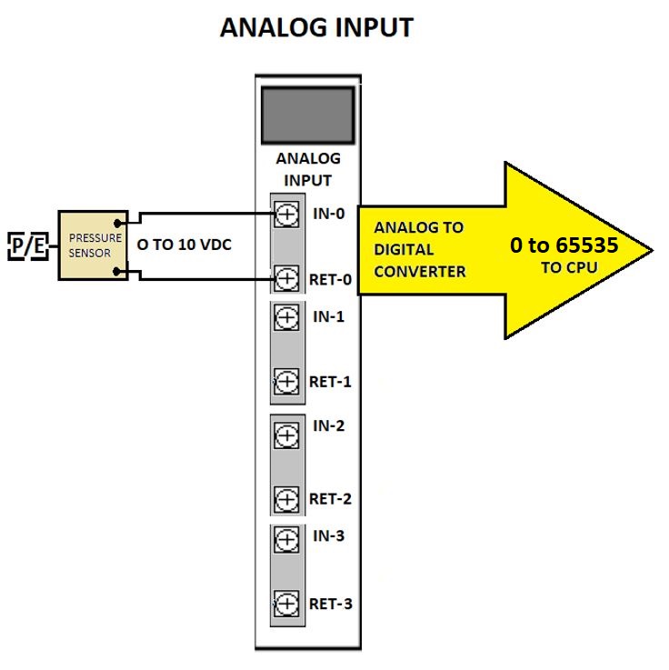
These devices provide proportional voltage or current signals that reflect their real-world measurements. For instance, a pressure sensor might output a 0-10 VDC signal to represent measured pressure. Inside the PLC, an analog-to-digital converter (ADC) processes this continuous signal and converts it to digital data, which the PLC then reads and uses in its control logic.
Analog Outputs: Controlling the Process
On the output side, analog signals enable the PLC to influence processes with smooth adjustments, rather than abrupt on/off control. Examples of analog output devices include:
- Control valves for regulating flow or pressure
- A speed reference signal transmitted to a variable speed drive to control motor speed
Analog outputs can send proportional current or voltage signals that tell these devices exactly how much to open, close, speed up, or slow down. Within the PLC, a digital-to-analog converter (DAC) takes the digital commands from the PLC’s program and converts them into a smooth analog signal for the device.

Key Considerations for Analog I/O
- Voltage and Current Ranges: Always verify that the PLC’s analog I/O modules are compatible with the voltage or current range of the connected devices. Mismatched ranges can lead to inaccurate readings or equipment damage.
- Signal Integrity: Analog signals are more sensitive to electrical noise, so ensure proper shielding and grounding for wiring connections.
- Calibration: Regularly calibrate sensors and actuators to maintain accuracy in your system.
Analog I/O capability in PLCs greatly extends their functionality, making it possible to control complex processes that require fine-grained adjustments. With the right configuration, your PLC becomes a powerful tool for seamless, real-time control across variable conditions.
If you find this discussion of PLC basics interesting, then you might want to take a look at this course on Udemy called the Pre PLC Programming Course. These blogs are based on material from that course. It is not geared toward any particular brand of PLC our programming software. The fundamentals are relevant to all types of PLCs.
Up Next – Understanding Numbering Systems in PLCs