
Welcome to the next level in our learning series. The subject is Ladder Programming With PLC Timers Counters and Triggers. The prerequisite for this material is our previous part in the learning series, PLC Part 3 Basic Ladder Diagram. The exercises for this series are designed to work with the DIY PLC Training station but you can cover a lot of the material using the CODESYS built in simulator if you chose. Using the CODESYS simulator is discussed in Exercise 5.
To get an idea what’s covered here, take a peek at the table of contents. You’ll see that we start with Timers and work our way up to Counters.
Table of Contents
The Timers: TON And TOF Function Blocks
TON, for timer on delay, is a predefined function block. It is assigned a special data type named TON.
Made up of:
- Boolean input, IN, to monitor network input signal
- Boolean output, Q, to supply output signal
- Operand, PT, the timer preset.
- Operand, ET, the timer elapsed time
When the TON input state, at IN transitions from FALSE to TRUE, the timer starts, and the elapsed time is incremented at ET. When the elapsed time (ET) reaches the preset value (PT), The output state at Q transitions to TRUE and the elapsed time at ET stops incrementing.
When the TON input state, at IN transitions from TRUE to FALSE, The output state at Q will be FALSE and the elapsed time at ET is set to 0. At this point the TON will be reset and ready for a repeat cycle.

Data from the TON is available to use elsewhere within the POU as .IN, .Q, .PT, and .ET after the variable name. For example if the variable name is TON_0 then TON_0.IN, TON_0.Q, TON_0.PT and TON_0ET can access the respective data.
TOF, for timer off delay, is a predefined function block. It is assigned a special data type named TOF.
Made up of:
Boolean input, IN, to monitor network input signal
Boolean output, Q, to supply output signal
Operand, PT, the timer preset.
Operand, ET, the timer elapsed time
When the TOF input state, at IN transitions from FALSE to TRUE, the output state at Q transitions to TRUE and the elapsed time at ET is set to 0.
When the TOF input state, at IN transitions from TRUE to FALSE, the timer starts, and the elapsed time is incremented at ET. When the elapsed time (ET) reaches the preset value (PT), The output state at Q transitions to FALSE and the elapsed time at ET stops incrementing.

Data from the TOF is available to use elsewhere within the POU as .IN, .Q, .PT, and .ET after the variable name. For example if the variable name is TOF_0 then TOF_0.IN, TOF_0.Q, TOF_0.PT and TOF_0ET can access the respective data.
Exercise 12 – Light Switch #3
In this exercise, we’ll resume from where we left off in Exercise 11, continuing with the project “Lightswitch”. The project will be run on the PLC training station, demonstrating a TON timer example. Simultaneously, we’ll explore declaring variables that are not linked to specific addresses and understanding the appropriate syntax for expressing time.
Our task is this: The lights in the green room are frequently left on for hours with no one in the room. People are forgetting to turn the lights off and electricity is being wasted. We will make an addition to the program to automatically turn off the lights after 2.5 hours.

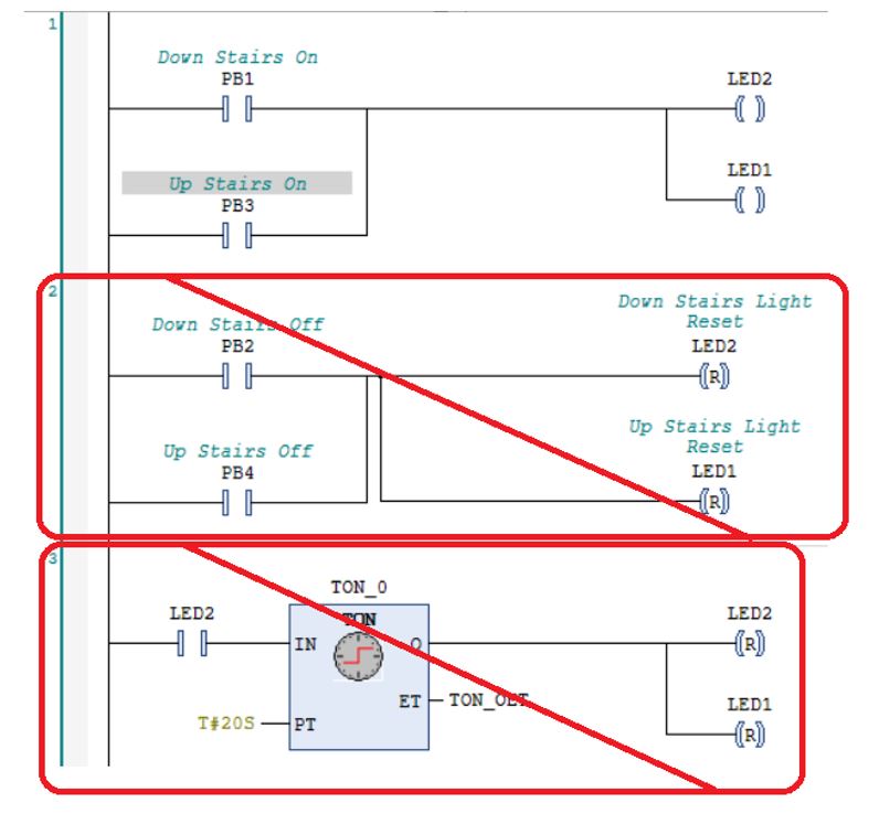
Starting at the workspace. The ladder logic from Exercise 11 is visible. PB3 and PB4 have been added for the upstairs light control as requested at the end of Exercise 11.
Notice that PB3 has been declared as address %IX0.2 and data type BOOL.
Notice that PB4 has been declared as address %IX0.3 and data type BOOL.
This is not the only way to solve the problem from Exercise 11, but you may want to make your logic similar, to continue with this exercise.

Create a new network 3. Find the TON and place it on the new network.

When the TON lands on the network, you may notice that a Contact is placed to the left by default. It is optional and can be deleted or replaced if you chose. A variable name is suggested for the timer, “TON_0”, highlighted in grey.
If you press the Enter key or click anywhere in the workspace, the Auto Declare Box appears prompting you to declare the variable name TON_0 as data type TON. In this example we will not enter an address. We do not need to link the timer to a specific address. Click OK to proceed.

To edit the operands for the TON, click where you see the three question marks (???) then type in the desired text.
Note: If the Auto Declare box does not appear automatically, you can prompt it by selecting the desired text and pressing the Shift and F2 buttons at the same time.
To set the timer preset (PT) there is a syntax applied. The syntax helps the PLC recognize the value is expressed as data type TIME. The prefix is T#, then a numerical quantity. Finally, the letter D, H, M, S or MS for the unit of time. An example for 20 seconds is shown in the diagram titled Time Data Type.

Time can be expressed in different units. D for day, H for hour, M for minute, S for second or MS for milliseconds. The unit of time can be entered in upper or lower case.
For Example:
- T#20S and T#20s are both acceptable
Time can be expressed in multiple units but the order must be larger units to the left and smaller to the right.
For Example:
- Acceptable T#19S400MS T#2m30S T#4M400MS T#1d4h20m12s
- Not Acceptable T#400MS19S T#30s2m T#400MS4M T#12s20m4h1d
A good rule of thumb, to avoid possible overflow problems, is for smaller units on the right is to stay within limits. 999ms, 59sec, 59min, 23hr.
For Example:
- T#2m30S or T#150S are good. T#1m90S is not so good.
The TIME data type lower and upper limits are T#0d0h0m0s0ms (0ms) to T#49d17h2m47s295ms (almost 50 days).
Timer presets can also be assigned declared variables that are the TIME data type. We will see an example in another exercise.
In this exercise, for TON_0. We will set the PT operand to 20 seconds (T#20S) for now. When we are testing the logic, we don’t want to wait 2.5 hrs to see if the lights go out. The PT operand can be increased after the test.

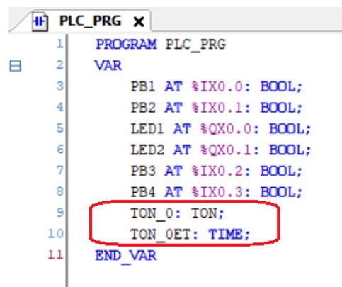
The elapsed time operand, ET, is data that could be used in ladder logic but we do not need the data for our example. We will assign a variable though, so we have a place to watch the timer increment. You can name it anything you want really but in this example we will type in the name TON_0ET. It makes sense because the name includes the timer variable and the operand.

If you press the Enter key or click anywhere in the workspace, the Auto Declare Box appears prompting you to declare the variable name TON_0ET as data type TIME. In this example we will not enter an address. We do not need to link the elapsed time operand to a specific address. Click OK to proceed.

In the declaration editor we see new declarations for TON_0 and TON_0ET have been added to the local variables defined for the program PLC_PRG. Notice the new declarations do not contain the AT code to link a specific address. We don’t need a specific address to make the timer work, so it is of little concern to us. This way the computer can decide what memory to allocate.
Place a Reset Coil instruction on the network to the right. Then place second Reset Coil. Assign the variables for the lights the Reset Coil instructions. Then assign a variable for one of the lights to the Contact at the left of the network. Remember that variables LED1 and LED2 were already declared in a previous exercise.

Take the usual steps to get logged in to the soft PLC, with the application loaded and running with slave device. Once the application is running. Monitor the logic status from the workspace display.
Observe, when PB1 is pressed the lights switch on. When LED2 (or LED1) for the light is TRUE, IN at TON_0 is TRUE and the timer starts timing.

When the timer reaches the preset of 20 seconds, Q at TON_0 becomes TRUE, activating the Reset Coil for LED2 and LED1. It happens so fast you can’t really see it. When LED2 (or LED1) is no longer TRUE, IN at TON_0 becomes FALSE. The timer is ready to do it all over again.

The ladder logic meets the goal to turn off the lights after a set time limit. It is a good time to save the project. This concludes Exercise 12.
Exercise 13 – Light Switch #4
In this exercise we will modify the existing project, “Lightswitch”. The project will be run on the PLC training station. A TOF timer example will be demonstrated. At the same time, we will practice declaring variables without the help of the Auto Declare Box.
Our task is this: Now that the lights turn off automatically, no one is using the off buttons anymore. Might as well get rid of them. Redesign the ladder logic to use the 2 pushbuttons, PB1 and PB3, to turn on the lights, LED2 and LED1. The lights are to automatically turn off after 2.5 hours have passed.

Starting at the workspace. The ladder logic from Exercise 12 is visible. Change the Set Coils for LED2 and LED1 to Coils.

Our intention is to eliminate the off buttons so PB2 and PB4 can be removed from the logic. This exercise is a demonstration of the TOF timer so the TON, TON_0, is no longer required either.
Removing networks 2 and 3 will get rid of the unused instructions.
(Hint: Clicking on the network will highlight it. Then right click and select delete)
We wish to add a TOF to the logic. Variables will be required for the TOF and for the elapsed time operand, ET. For this exercise we will add the new variables directly to the declaration editor. There are two different views for the declaration editor that can be selected at the upper right of the window. There is a tabular view and a textual view When declaring variables from the textual view, there is a syntax that must be applied. It may or may not include the AT Code depending on whether a specific address will be linked.
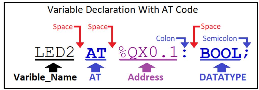
The diagram labelled Variable Declaration With AT Code shows the variable LED2, for the yellow LED, as an example. Notice the AT Code and the address are included to specify an address.
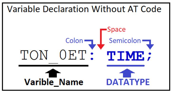
The diagram labelled Variable Declaration Without AT Code shows the variable TON_0ET, from the TON ET operand, as an example. Notice there is no AT Code or address.
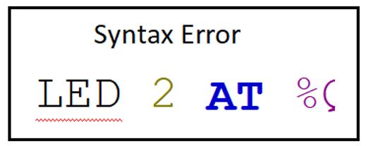
Pay attention to spaces, colons and semicolons. If the declaration syntax is not correct the variable name will be highlighted with a red wavy line. Remember variable names cannot have spaces.
From the declaration editor we can see the variables declared so far.
Notice the declarations appear between the keywords VAR and END_VAR. This means the scope of the variables is, VAR, for normal variables.
Notice the text PLC_PRG in the tab title at the top of the declaration editor and to the right of the keyword PROGRAM. This means that the variables are valid within the POU named PLC_PRG.
Remember what we learned about the scope and object fields for the Auto Declare Box from Exercise 11.
To add to the current list of variables we must insert new declarations between the keywords VAR and ENDVAR. To begin the declaration, we will use the mouse to place the cursor at the end of the last variable showing.

Then press the enter key to start the next line. We will add a variable named TOF_0 by typing in the variable name immediately followed by a colon and then a space. Then type in the data type, TOF, immediately followed by a Semicolon. Then press the enter key again.
Now add a variable named TOF_0ET by typing in the variable name with colon and space. Then the data type, TIME with semicolon. Remember the syntax. Spaces, colons and semicolons must be in the proper place
.

At this point you have completed declaring the new variables.
Place a TOF on network 1. To use the drag and drop method, find the TOF and place it where the green arrow appears on the network.

When the TOF lands on the network, you may notice that a variable name is suggested for the timer, TOF_1. We are not using that variable name. We will use the variable name that we have recently declared. Type in TOF_0 instead. If the Auto Declare Box appears click Cancel and then type in the variable name.

We will set the PT operand to 20 seconds (T#20S) while we test the logic. The PT operand can be increased after the test. Type in the variable name TOF_0ET for the ET operand.

Take the usual steps to get logged in to the soft PLC, with the application loaded and running with slave device. Once the application is running. Monitor the logic status from the workspace display.
Observe, when PB1 is pressed, Q becomes TRUE and the lights switch on. Notice that so long as the button is pressed the elapsed time is Zero.

When the button is released, the light remains on. The elapsed time begins to increment as the timer starts timing.

When the timer reaches the preset of 20 seconds, Q at TOF_0 becomes FALSE and switches the lights off. The elapsed time remains at 20 seconds. The timer is ready to do it all over again.

The same happens when PB3 is pressed. When the ladder logic has passed the test. We can adjust the preset, in edit mode, to 2.5 hours.

The ladder logic meets the goal to turn off the lights after a set time limit. This is a good time to save your work. This concludes Exercise 13.
Common Timer Applications
This section provides some suggested logic to use timers for different functions. What is suggested for each application may not be the only way to get the desired result. But it should be helpful if you are just getting started.
If you like, you can start fresh with a copy of project “Training_Station_Base” saved with a new name and practice building these networks with the ladder editor. Maybe try testing the logic with the simulator or the training station.
Free Running Timer
In this example TON_0 will run continuously in a 20 second cycle.
When Q is FALSE the negated contact to the left of the TON is TRUE. The TON will run with elapsed time incrementing until the preset time is reached. Then Q becomes TRUE, the negated contact to the left of the TON will become FALSE, just long enough to reset the timer and start the next cycle.
Q and CoilX are only TRUE for one scan each 20 second cycle.

Flasher
In this example 2 timers will sequence an event, flashing LED1 on and off. TON_0 determines how long the LED is off and TON_1 determines how long the LED is on.
The Flasher Off Time
When Q for TON_1(TON_1.Q) is FALSE, the negated contact to the left of TON_0 is TRUE. TON_0 will run with elapsed time, TON_0ET, incrementing until the preset time of 1 second is reached. When TON_0.Q becomes TRUE the LED will switch on.
The Flasher On Time
At the moment TON_0.Q becomes TRUE and the LED is lit, the contact to the left of TON_1.IN becomes TRUE. TON_1 will run with elapsed time, TON_1ET, incrementing until the preset time of 1 second is reached. When TON_1.Q becomes TRUE, the negated contact to the left of TON_0 is FALSE. TON_0ET, will be reset to zero, TON_0.Q becomes FALSE and the LED will switch off.
Flasher Timers Reset
At the moment TON_0.Q becomes FALSE and the LED switches off. The negated contact to the left of TON_1.Q becomes FALSE. TON_1ET, will be reset to zero. The flasher cycle has completed and will start all over again.

You may have noticed something with the flasher example. That the block for TON_1 on network 2 is missing the “Q” and the “ET” is in its place.

When working in the ladder editor you can cleanup unused operands by clicking the function block to highlight it and then right clicking and selecting Remove Unused FB Call Parameters.

Flasher – Alternating 2 Outputs
The flasher logic is easily modified to control two events, flashing 2 LEDs alternately, by adding a network.
The example shown here operates the same as the flasher already discussed. The exception is the final network with the negated contact for TON_0.Q and coil for LED2.
We can see at network 1 that when TON_0.Q is FALSE then LED1 is off and when TON_0.Q is TRUE then LED1 will be off.
At the same time when TON_0.Q is FALSE the negated contact on network 3 is TRUE so LED2 will be on and when TON_0.Q is TRUE then LED2 will be off.
In this relationship LED2 will always be the opposite of LED1. So, as LED1 flashes on then off, LED2 will alternately flash off then on.

The flasher arrangement can sequence multiple events by adding more timers to the loop.
One Shot Timer – Limited Duration
In this example the coil for LED1 is limited to 2 seconds of ON Time.
If PB1 is pressed and held, LED1 will light for 2 seconds. Then when the TON has reached the timer preset the negated contact for TON_0.Q will become FALSE and LED1 will switch off.
If PB1 is pressed for less than 2 seconds, LED1 will be on when PB1 is pressed and off as soon as PB1 is released.

One Shot Timer – Fixed Duration
In this example the coil for LED1 will be on for 2 seconds if PB1 is pressed momentarily or held.
If PB1 is pressed and held, LED1 will light for 2 seconds. Then when the TON has reached the timer preset the negated contact for TON_0.Q will become FALSE and LED1 will switch off.
If PB1 is pressed and released in less than 2 seconds, LED1 will be on when PB1 is pressed and remain on for 2 seconds.
The logic is similar to the One Shot Timer already discussed with limited duration. A branch has been added with the conditions that the TON is enabled (TON_0.IN) but has NOT reached the preset time (TON_0.Q). This branch will “Seal In” the LED and the TON from the time the timer starts timing until the preset time is reached.

Timer Timing
You may wish to control an output with a timer but with something different than On Delay or Off Delay. It was alluded to in the branch for the One Shot Timer Fixed Duration when we used conditions for the TON enabled but the preset NOT reached. This branch provided a “Seal In” function while the TON was timing.
TON Timer Timing
The diagram labelled TON Timer Timing is an example where LED1 will be on while the TON_0 is timing. The instructions for network 2 will be TRUE if TON_0.IN is TRUE and TON_0.Q is FALSE.

TOF Timer Timing
The diagram labelled TOF Timer Timing is an example where LED1 will be on while the TOF_0 is timing. Notice the conditions differ for TOF compared to TON. The instructions for network 2 will be TRUE if TOF_0.IN is FALSE and TON_0.Q is TRUE.

The Triggers: Edge Detection Instructions, R_TRIG And F_TRIG Function Blocks
While editing, the Edge Detection command can add rising edge trigger or falling edge trigger to contacts and network segments while editing.
A contact with rising edge detection will monitor the bit of the variable assigned to the contact.
The instruction condition will be FALSE if the bit is FALSE ( OFF, equals 0).
The instruction condition will be TRUE for one scan only when the bit transitions to TRUE (ON, equals 1).

If rising edge detection is added to a network segment, when network conditions to the left transition from FALSE to TRUE, the state to the right will be TRUE for the duration of one PLC scan.

A contact with falling edge detection will monitor the bit of the variable assigned to the contact.
The instruction condition will be FALSE if the bit is TRUE ( ON, equals 1).
The instruction condition will be TRUE for one scan only when the bit transitions to False (OFF, equals 0).

If falling edge detection is added to a network segment, when network conditions to the left transition from TRUE to FALSE, the state to the right will be TRUE for the duration of one PLC scan.

The function blocks for R_TRIG and F_TRIG perform actions similar to the the edge detections described. The Function blocks are assigned a variable name that is useful if you want to use the trigger generated in other networks of your logic.
R_TRIG, for rising edge trigger, is a predefined function block. It is assigned a special data type named R_TRIG.
Made up of:
- Boolean input, CLK, to monitor network input signal
- Boolean output, Q, to supply output signal
When the R_TRIG input state, at CLK transitions from FALSE to TRUE, it’s output state, at Q, will be TRUE for the duration of one PLC scan.

F_TRIG, for falling edge trigger, is a predefined function block. It is assigned a special data type named F_TRIG.
Made up of:
- Boolean input, CLK, to monitor network input signal
- Boolean output, Q, to supply output signal
When the F_TRIG input state, at CLK transitions from TRUE to FALSE, it’s output state, at Q, will be TRUE for the duration of one PLC scan.

Exercise 14 – Light Switch #5
In this exercise we will modify the existing project, “Lightswitch”. The project will be run on the PLC training station. Trigger examples will be demonstrated.
Our task is this: Now that the 2.5 hour timer has been implemented for the light control, some sneaky person has devised a way to defeat the timer. Jamming a paper clip into PB1 keeps the switch closed continuously. The lights do not turn off after the time limit. We must come up with a fix to overcome this dirty trick and discourage people from doing this.

Remember from Exercise 13, when PB1 is pressed, Q becomes TRUE and the lights switch on. Notice that so long as the button is pressed the elapsed time is Zero.

We can use Edge Detection to respond to the PBs when they transition between off and on. This will ignore the continuous state of the inputs and seems like a solution to our problem.
So, how do we apply edge detection? The Edge Detection command will toggle a selected ladder element between 3 states: rising edge detection, falling edge detection and then back to no edge detection applied.
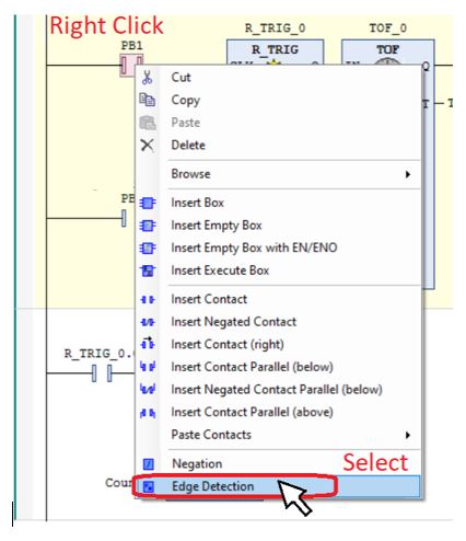
The command is easily available in 3 places:
1 . Select Edge Detection from the toolbar.

2 . Select from the FBD/LD/IL dropdown menu.

3 . Right click on the network being edited, a menu will appear with a list of instructions.
Now we know how to use the Edge Detection command, let’s test some logic changes and see what works best.
To begin, open the project “Lightswitch” and from the editor workspace we should see the logic as we left it from Exercise 13. Change the preset to 20 seconds for testing. We can set it back to 2.5 hours after the test.

In this example we will use the toolbar method. Click on the network to highlight the area to the left of the TOF. Then click on the Edge Detection command on the toolbar.

The rising edge detection symbol will appear to the left of the TOF.

Take the usual steps to get logged in to the soft PLC, with the application loaded and running with slave device. Once the application is running. Monitor the logic status from the workspace display.
Press and hold PB1. Observe, that Q becomes TRUE and the lights switch on. Notice that the TOF is timing and the elapsed time is incrementing even though the PB is held. Release and press PB1 again, the elapsed time resets to zero and timing starts all over again. When the timer times out the lights go out.

It works the same for PB3. This seems like the solution to our problem. But there is a flaw. This time press and hold PB3 to represent the PB with the paper clip jammed in. At the same time press and releasing PB1. The PB being pressed and released does not reset the elapsed time to zero. When the lights turn off at the end of the timer cycle PB1 cannot turn the lights back on. We need a better solution.
Logout to return to edit mode. To remove the rising edge detection symbol, click to highlight and then click the Edge Detection command. Clicking once will change to falling edge detection and clicking the second time will remove the edge detection.

Now highlight the contact for PB1 and click the Edge Detection command. The symbol for contact with rising edge detection will appear. Repeat for PB3

Logon to connect to PLC and download online changes. Repeat the test, holding one PB while pressing and releasing the other. The PB that is pressed and released will now reset the elapsed time to zero. This is the solution to our problem.
For curiosity’s sake, change one of the PBs to Falling Edge Detection and test the logic. How does it behave differently?
When the test is complete, logout. Set the preset back to 2.5 hours and then save the project. This concludes Exercise 14.
The Counters: CTU And CTD Function Blocks
CTU, called the Up Counter, is a predefined function block. It is assigned a special data type named CTU.
Made up of:
- Boolean input, CU, to monitor network input signal
- Boolean input, REST, to reset the count to zero
- Boolean output, Q, to supply output signal
- Operand, PV, the counter preset. Range of 0 to 65535
- Operand, CV, the incremented counter value. Range of 0 to 65535
Each time the input state, at CU transitions from FALSE to TRUE, at the rising edge, the counter increments the numeric value of CV by 1. When the value of CV counts up to the value of the preset or greater then Q will be TRUE. If CV reaches the upper limit of 65535 then it will not increment any higher.

Data from the CTU is available to use elsewhere within the POU as .CU, .Q, .PV,.RESET and .CV after the variable name. For example if the variable name is CTU_0 then CTU_0.CU, CTU_0.Q, CTU_0.PV, CTU_0.RESET and CTU_0.CV can access the respective data.
CTD, called the Down Counter, is a predefined function block. It is assigned a special data type named CTD.
Made up of:
- Boolean input, CD, to monitor network input signal
- Boolean input, LOAD, to reset the count to preset value
- Boolean output, Q, to supply output signal
- Operand, PV, the counter preset.
- Operand, CV, the decremented counter value
Each time the input state, at CD transitions from FALSE to TRUE, at the rising edge, the counter decrements the numeric value of CV by 1. When the value of CV counts down to the 0 Q will be TRUE. Once CV reaches the lower limit of 0 then it will not decrement any lower.

Data from the CTU is available to use elsewhere within the POU as .CD, .Q, PV, .LOAD and .CV after the variable name. For example if the variable name is CTD_0 then CTD_0.CD, CTD_0.Q, CTD_0.PV, CTD_.LOAD and CTD_0.CV can access the respective data.
Exercise 15 – Light Switch #6
In this exercise we will modify the existing project, “Lightswitch”. The project will be run on the PLC training station. A counter examples will be demonstrated and we will learn about internal flag memory.
The situation is this: The fix is in place, jamming the push buttons will no longer keep the lights on beyond the 2.5 hour limit. But it seems that someone, who doesn’t know any better is still tampering with the system. At times, we still find paper clips jammed in the PBs. Our job is to collect the data. We need to devise a way to detect if PBs are tampered with and we want to know how many times it is happening. PB4 is assigned as a reset button to reset the data.
To begin, open the project “Lightswitch” and from the editor workspace we should see the logic as we left it from Exercise 14.

First, we will work on detecting the events when tampering occurs with the buttons. If a button is jammed then we can expect the switch will be closed longer than normal. We will make use of a timer to monitor how long the pushbuttons remain closed.
Create a new network #2 and place the ladder elements: Contacts, TON and Set Coil as shown in the diagram titled Network # 2.

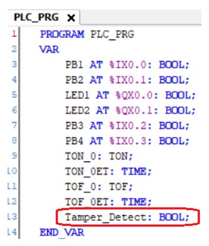
To assign a variable to the set coil, click where you see the three question marks (???) then type “Tamper_Detect”

If you press the Enter key or click anywhere in the workspace, the Auto Declare Box appears prompting you to declare the variable name Tamper_Detect as data type BOOL. In this example we will not enter an address. We do not need to link the variable for the coil to a specific address. It is not connected to a real-world output. Click OK to proceed.

Internal Memory Flags
Internal Memory Flags, sometimes referred to as Internal Contacts or Internal Coils are not connected to real world I/O. They serve as imaginary I/O that can be assigned to Contacts and Coils. In this example we have declared an internal flag named Tamper_Detect.
In the declaration editor we see new declaration for Tamper_Detect has been added to the local variables defined for the program PLC_PRG. Notice the new declaration does not contain the AT code to link a specific address.
To complete network # 2. Assign the rest of the variables as shown in diagram titled Network #2 Variables. Remember that variables PB1, PB3, TON_0 and TON_0ET were already declared in a previous exercise. Set the timer preset to 10 seconds.

Create network #3 with a Contact for PB4 and Reset Coil for Tamper_Detect. Remember that variable PB4 was already declared in a previous exercise.

Take the usual steps to get logged in to the soft PLC, with the application loaded and running with slave device. Once the application is running. Monitor the logic status from the workspace display.
Observe, the logic works as before, when PB1 or PB3 are pressed and released, the lights come on and the elapsed time, TOF_0ET, begins to increment.
However, if PB1 or PB3 are pressed and held, TON_0 begins timing. When the elapsed time at TON_0ET reaches 10 seconds the Set Coil sets the variable Tamper_Detect as TRUE. It seems reasonable that if one of the PBs were jammed then the switch would be cloded for at least 10 seconds. It looks like our tamper detection logic is working.
Pressing PB4 should reset the variable Tamper_Detect back to the FALSE value, ready to start the detection process again.

After testing the tamper detection logic, logout to return to edit mode. The next objective is to track the number of events when tampering occurs with the buttons. We can do this by adding a counter, to count up (CTU).
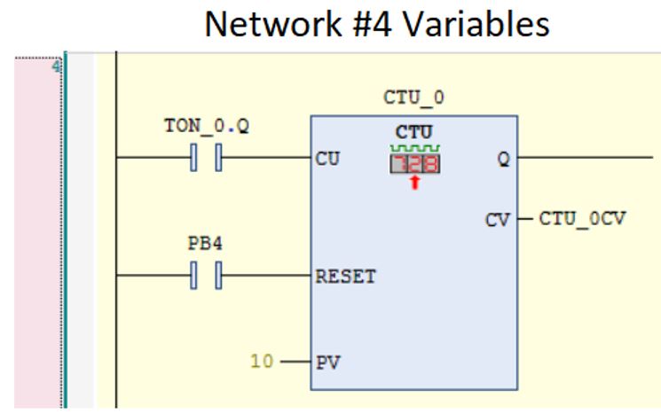
Create network #4 and place a CTU as shown in the diagram titled Network # 4.

When the Auto Declare Box appears it will prompt you to declare the variable name CTU_0 as data type CTU. In this example we will not enter an address. We do not need to link the CTU to a specific address. Click OK to proceed.

The counter value operand, CV, is data that could be used in ladder logic but we do not need the data for our example. We will assign a variable though, so we have a place to watch the counter increment. You can name it anything you want really but in this example we will type in the name CTU_0CV. It makes sense because the name includes the counter variable and the operand.

If you press the Enter key or click anywhere in the workspace, the Auto Declare Box appears prompting you to declare the variable name CTU_0CV as data type WORD. In this example we will not enter an address. We do not need to link the counter value to a specific address. Click OK to proceed.

In the declaration editor we see new declarations for CTU_0 and CTU_0CV have been added to the local variables defined for the program PLC_PRG. Notice the new declarations do not contain the AT code to link a specific address. We don’t need a specific address to make the counter work.

To complete network # 4. Assign the rest of the variables as shown in diagram titled Network #4 Variables. Remember that variables PB4, and TON_0 were already declared in a previous exercise. TON_0.Q is the output, Q, from TON_0
Set the counter preset to 10 seconds.
Take the usual steps to get logged in to the soft PLC, with the application loaded and running with slave device. Once the application is running. Monitor the logic status from the workspace display.
Observe, the logic works as before for the lights and tamper detection. What’s new is that when PB1 or PB3 are pressed and held, each time TON_0 reaches 10 seconds, CTU_01 increments by 1. We can see the counter value changing at CTU_0CV.

The ladder logic meets the goal to collect data from PB tampering events. This is a good time to save your work. This concludes Exercise 15.
Thank you for reading the learning series, PLC Part 4 Timers Counters & Triggers
Coming Soon – PLC Part 5 Working With Numbers
References – Books And Weblinks
You can explore more on the subjects discussed in PLC Part 3 Basic Ladder Diagram with these links.
CODESYS – Codesys help website – https://help.codesys.com/
Arduino Uno – Arduno Learn website – https://docs.arduino.cc/learn/