Welcome to our first learning series. The subject is Programable Logic Controllers for Industrial Automation and we are starting with the basics. The prerequisite for this material is basic electrical training, especially electrical safety, basic electrical circuits AC & DC and ability to read schematic drawings.

To get an idea what’s covered here, take a peek at the table of contents. You’ll see we start off with “What is a PLC?” and at the end we will be learning AND, OR and NOT operators to get into a programming mindset.
Table of Contents
What is a Programmable Logic Controller?
Commonly referred to as a PLC, it is a robust digital computing device used for controls and automation. The PLC receives input signals, processes the input data based on programmed instructions and then provides outputs required to control equipment. As the name implies, it is programmable. The instructions can be defined using a suitable programming language to create a user program and then loaded to the PLC memory.

When working in industrial automation and referring to programmable devices, other acronyms like PAC and IPC will come up. These are Programable Automation Controllers (PAC) and Industrial Personal Computers (IPC). These devices have similarities to PLCs like handling inputs, processing instructions and providing outputs. But there are differences as well.
PAC is a term applied to devices with more advanced features than common PLCs but in time PLC development tends to catch up. So sometimes it is hard to tell the difference.

IPCs run operating systems much like personal computers. This would include versions of Windows or Linux. This makes IPCs very flexible with many software tools available. An example could be an IPC that controls a machine and runs visualization software to provide a Human Machine Interface (HMI) like display to a touchscreen.
For the scope of this learning series, we will be referring mostly to PLCs
History
To better understand the benefits of PLCs it is helpful to review relay logic. Before PLCs were mainstream, controls were hardwired. These hardwired systems consisted of control panels and were filled with switches and relays. It was common to use relays to make simple logical control decisions. This method of implementing logic in electrical control circuits, based on relays wired in a particular formation, is known as relay logic.


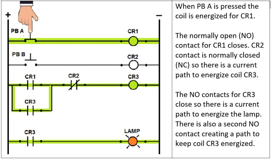

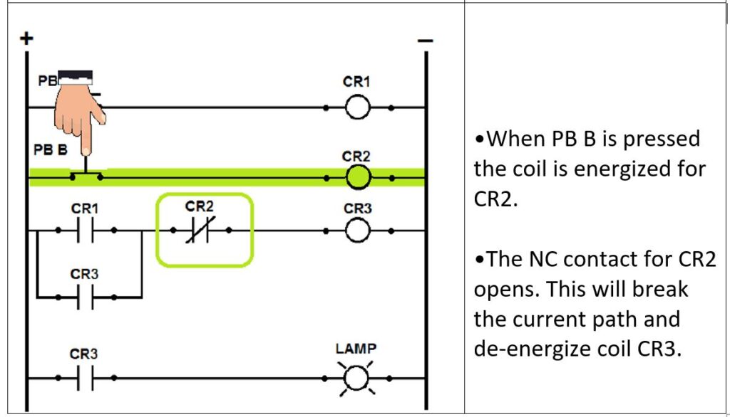
Our example of relay logic includes switches, relay contacts and coils. It also demonstrates a seal-in circuit to maintain CR3 after a momentary contact has closed and reopened.
The PLC was invented in 1968
To read an article about how Dick Morley invented the PLC Click Here.

Since then, they have become commonplace for industrial control.
PLCs replaced hardwired relay logic with software based, programable logic.
Advantages of PLC
• Cost effective for controlling complex systems.
• Flexible and can be reapplied to control other systems quickly and easily.
• Programmable and computer based allow more sophisticated control.
• Trouble shooting aids make programming easier and reduce downtime.
• Very reliable.
Ladder logic is a popular PLC programming language designed to resemble ladder schematic drawings.

The Parts Of A Basic PLC System
PLCs (or even PACs) come in different sizes and configurations.
Smaller systems are more limited, with fewer options and smaller quantities of Inputs/Outputs (I/O) available. These micro PLCs are suited to smaller machines.

Larger, modular systems are available with add-ons that can scale up to the largest of projects.

In each of these systems, there are common components and concepts.
The Most Essential Components
•Rack or Base Unit (modular system only) – Also sometimes called a backplane. For modular systems there needs to be a base to mount components like the power supply, CPU, I/O and other add-on modules.

•Power Supply -This could be external to the PLC or it may appear as a module that plugs into PLC mounting rack. Some smaller PLCs that are not modular will have the power supply built in. Power supplies are available with different input voltages depending on the specific line voltage required. Available input voltages include 24Vdc, 120Vac or 240Vac. The output voltage is the correct level to power PLC components This power supply, generally, should not power the field devices. Field devices are input devices, like switches, sensors and relay contacts, or output devices like indicator lights, solenoids, or relay coils. Field devices should be powered by a separate voltage source.

•CPU (Central Processing Unit) – The unit that houses the processor and memory that is the brain of the system.

Typically, programs and data are stored in Random Access Memory (RAM). This includes the user program and the status of inputs and outputs. RAM is volatile, which means data will be lost when power is removed. A PLC with RAM memory will have a battery backup.
The firmware and operating system are stored in non-volatile memory called Read Only Memory (ROM). These files are critical to basic processor function. That is why they are read only and not accessed by the user. If this data was to become corrupt it can turn the CPU into a “brick”!
To see an article about types of PLC memory click here.
To make firmware upgradable, some systems may have a special type of ROM known as Electrically Erasable Programable Read Only Memory (EEPROM) Firmware can be loaded using a process known as firmware flashing, where a specific procedure is followed to write a new firmware file. Firmware flashing is not for amateurs, remember the part about corrupt data BRICKING THE CPU!

Some PLCs are equipped with a user accessible EEPROM or an SD card to back up the user program. S
Somethings you might see on a CPU module include:
LED lights or a display to show the processor status with indications for Stop / Run status or Error status.
Communication ports, like ethernet or USB connectors to connect the PLC to a programming device or other network devices.
•Input / Output (I/O) Sections – It is the field devices that connect the PLC to the “real word” elements of a machine. Components in the field consist of devices connected to inputs like switches, sensors and relay contacts or devices connected to outputs like indicator lights, solenoids, or relay coils. This is not a complete list of field devices compatible with a PLC but it is a good start.
Termination points are required to connect field devices to the PLC. On smaller systems these terminals can be found on the main unit. Modular systems will have dedicated modules for wiring I/O. The input interface will convert the connected inputs into digital data for the processor. The Output interface will convert digital data from the processor for the connected outputs.

More On The Topic Of I/O
Where the CPU may seem to be more exciting, with RAM and ROM and processing power. It’s internal connections are already defined. The CPU is made up of components soldered to a circuit board. It is the I/O and connected devices that interact with the real world. That is where we are most “hands on” when installing or servicing PLC hardware.
Field devices can be electromechanical or semiconductor type. It is critical to wire these devices correctly. Understanding I/O and field wiring is a big part of working with PLCs.
Both inputs and outputs can be categorized into two groups: discrete I/O and analog I/O.
Discrete I/O
Sometime called digital I/O is concerned only with signals that are on or off.

When we say digital, it means that information is expressed as a series of 1s and 0s, on or off, true or false.
As far as inputs are concerned, we can make these statements:
A discrete input connected to a PLC that is in the OFF state, in the “real world”, will present a 0 to the PLC memory.
A discrete input connected to a PLC that is in the ON state, in the “real world”, will present a 1 to the PLC memory.
We can make similar statements for outputs:
A discrete output connected to a PLC defined as 0 in memory will be in the OFF state in the “real world”.
A discrete output connected to a PLC defined as 1 in memory will be in the ON state in the “real world”.
Discrete Inputs
Devices that are wired to discrete inputs like push buttons, toggle switches, relay contacts or proximity switches are all switching devices. These switching devices, when connected properly to PLC inputs, form electric circuits.
When a switching device is closed, current will flow and the input circuits will be ON. Based on our statement above, we know the PLC will logically interpret this as 1 in memory.
When the switching device opens, current is interrupted and the input circuit will be OFF. Based on our statement above, we know the PLC will logically interpret this as 0 in memory.

It is important to pay attention to the specifications of the device you connect your inputs to. Input modules come in different types. Attributes include operating voltage, sinking / sourcing (direction of current flow) and number of inputs.
To appreciate the different type of discrete inputs available, let’s consider some different input modules available for Allen Bradley 1756 series.
Table of AB 1756 series Discrete Input Modules
| Part Number | Description | Number of Inputs | Voltage Category |
| 1756-IA8D | 120V AC diagnostic input module | 8 | 120V AC 50/60 Hz |
| 1756-IA16 | 120V AC input module | 16 | 120V AC 50/60 Hz |
| 1756-IA16I | 120V AC isolated input module | 16 | 120V AC 50/60 Hz |
| 1756-IA32 | 120V AC input module | 32 | 120V AC 50/60 Hz |
| 1756-IB16 | DC (10…31.2V) input module | 16 | 12/24V DC sink |
| 1756-IB16I | DC (10…30V) isolated input module | 16 | 12/24V DC sink/source |
| 1756-IB32 | DC (10…31.2V) input module | 32 | 12/24V DC sink |
| 1756-IC16 | DC (30…60V) input module | 16 | 48V DC sink |
| 1756-IG16 | TTL input module | 16 | 5V DC TTL source (Low=True) |
| 1756-IH16I | 125V DC isolated input module | 16 | 125V DC sink/source |
| 1756-IM16I | 240V AC input module | 16 | 240V AC 50/60 Hz |
| 1756-IN16 | AC (10…30V) input module | 16 | 24V AC 50/60 Hz |
| 1756-IV16 | DC (10…30V) sourcing input module | 16 | 12/24V DC source |
| 1756-IV32 | DC (10…30V) sourcing input module | 32 | 12/24V DC source |
A full list of AB 1756 I/O modules and details can be seen here.
Number of inputs:
We can see input modules are available with as few as 8 inputs and as many as 32.
Voltage:
Here is an important safety reminder! Never assume, just because you are working on PLC control circuits, that you are working with safer, lower, voltages. You could get a nasty shock. In fact, it could be a lethal one. Make sure you understand important details about the equipment you are working on. Including the control voltages.
For DC voltages we see as low as 5VDC for TTL up to 125VDC.
For AC voltages, there are input modules that handle 120 VAC and 240 VAC.

Sinking / Sourcing:
From the table we can see some DC input modules categorized as Sink or Source. To connect devices to DC inputs correctly, we need to understand the concept of sinking and sourcing. The difference between the two is the direction of current flow.
Present day, it is understood that electrons flow from negative (-) to positive (+). However, the conventional direction of current flow is considered to be positive to negative. This notion comes from earlier days when those who pioneered the use of electricity recognized that electrical current was the movement of electrical charges through a conductor and then took a wild guess as to what direction. (They had a 50/50 chance).

The explanation of sinking and sourcing is based on conventional current flow. Positive potential is considered the “source” and negative potential is considered the “sink”.
Consider the diagram labelled Field Wiring For DC Sourcing Input Module below. The input module common terminal is connected to the positive. The switching devices are connected to the negative. In this configuration the input module is the electrical source. The red arrows indicate the conventional direction of current flow.

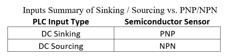
If a semiconductor field device is used, the DC sourcing input module is suitable for connection to NPN type sensors. A typical NPN sensor would have three leads. Two power leads to connect to positive and negative, then a third lead that produces a negative signal during an ON state.

Next, consider the diagram labelled Field Wiring For DC Sinking Input Module. The input module common terminal is connected to the negative. The switching devices are connected to the positive. In this configuration the switching devices are the electrical source. That make the input module the sink. The red arrows indicate the conventional direction of current flow.

If a semiconductor field device is used, the DC sinking input module is suitable for connection to PNP type sensors. A typical PNP sensor will have three leads. Two power leads to connect to positive and negative, then a third lead that produces a positive signal during an ON state.

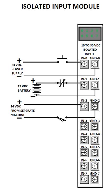
Isolated Inputs:
An isolated input module can be connected to devices from different power sources.
Some isolated inputs modules are suitable for connection as sinking and/or sourcing. In the diagram below, input 0 and input 1 are wired as sinking inputs and input 2 is wired as sourcing.
Discrete Outputs
Devices wired to discrete outputs like indicator lights, solenoids, or relay coils are load devices. These load devices, when connected properly to PLC outputs, form electric circuits. It is the PLC outputs that will act as switching devices for each load device. Generally, there are three basic types of hardware doing the switching. That would be transistors, triacs and relay contacts. A transistor is a semiconductor device for switching DC. A triac is a semiconductor device that switches AC. Relay contacts can handle both AC and DC as well as higher currents but relays have a mechanical reaction time so they are slower than semiconductors.
Based on our statement for discrete outputs we know if the PLC memory for the assigned output is set to 1 the output will be in the ON state. When a PLC output is ON, current will flow and the load device will be energized.
Again, based on our statement for discrete outputs we know if the PLC memory for the assigned output is set to 0 the output will be in the OFF state. When a PLC output is OFF, current is interrupted and the load device will be de-energized.

Specifications of the device you connect to the loads can be critical. PLC outputs are available in different types. Attributes include operating voltage, sinking / sourcing and number of outputs.
To appreciate the different type of discrete outputs available, let’s consider some different output modules available for Allen Bradley 1756 series.
Table of AB 1756 series Discrete Output Modules
| Part Number | Description | Number of Outputs | Voltage Category |
| 1756-OA8 | 120/240V AC output module | 8 | 120/240V AC 50/60 Hz |
| 1756-OA16 | 120/240V AC output module | 16 | 120/240V AC 50/60 Hz |
| 1756-OA16I | 120/240V AC isolated output module | 16 | 120/240V AC 50/60 Hz |
| 1756-OB8 | DC (10…30V) output module | 8 | 12/24V DC source |
| 1756-OB8I | DC (10…30V) isolated output module | 8 | 12/24V DC source |
| 1756-OB16I | 24V DC isolated output module | 16 | 12/24V DC sink/source |
| 1756-OB32 | DC (10…31.2V) output module | 32 | 12/24V DC source |
| 1756-OC8 | DC (30…60V) output module | 8 | 48V DC source |
| 1756-OG16 | TTL output module | 16 | 5V DC TTL (Low=True) |
| 1756-OH8I | DC (90…146V) isolated output module | 8 | 125V DC sink/source |
| 1756-ON8 | 24V AC output module | 8 | 24V AC 50/60 Hz |
| 1756-OW16I | AC (10…240V) DC (5…125V) isolated contact module | 16 | 5…125V DC or 10…240V AC |
| 1756-OX8I | AC (10…240V) DC (5…125V) isolated contact module | 8 | 5…125V DC or 10…240V AC |
A full list of AB 1756 I/O modules and details can be seen here.
Number of Outputs:
We can see Output modules are available with as few as 8 inputs and as many as 32.
Voltage:
Remember, electric shock can be deadly!
For DC voltages we see as low as 5VDC for TTL up to 125VDC.
For AC voltages, there are output modules that handle up to 240 VAC.

Sinking / Sourcing:
From the table we can see some DC output modules categorized as Sink or Source. To connect devices correctly, we need to understand the concept of sinking and sourcing for DC outputs. As stated for inputs, the difference is the direction of current flow.
Remember, conventional current flow is from positive to negative. Positive potential is considered the “source” and negative potential is considered the “sink”.
Consider the diagram labelled Field Wiring For DC Sourcing Output Module below. The output module common terminal is connected to the positive. The load devices are connected to the negative. In this configuration the output module is the electrical source. The red arrows indicate the conventional direction of current flow.

Next, consider the diagram labelled Field Wiring For DC Sinking Output Module. The output module common terminal is connected to the negative. The load devices are connected to the positive. In this configuration the load devices are the electrical source. That make the output module the sink. The red arrows indicate the conventional direction of current flow.

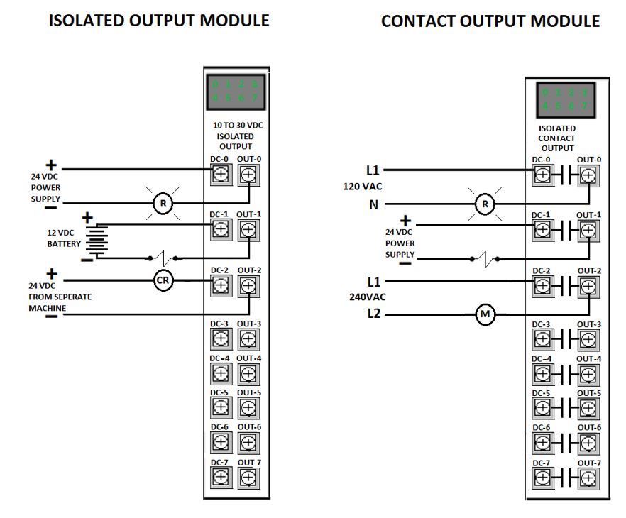
Isolated and Contact Outputs:
An isolated output module can be connected to devices from different power sources.
Some isolated output modules are suitable for connection as sinking and /or sourcing. In the diagram, labelled Isolated Output Module, output 0 and output 1 are wired as sourcing outputs and output 2 is wired as sinking.
Contact outputs use relays internally to provide a “dry-contact” switching output. Contact outputs can be used in similar fashion to an actual relay contact. Provided the contacts are rated for it, different power sources can be connected to each output, including AC or DC.
Analog I/O
Where discrete I/O signals are either on or off, analog inputs and outputs can be on, off or anywhere in between. Analog signals represent a continuously variable physical quantity.

Think of a Low Fuel warning light on your automotive instrument cluster as a discrete signal and the fuel gauge as an analog one.

For many process control applications the PLC must receive and produce analog signals. These signals are variable voltages or currents within one of the standard ranges below:
- 0 to 20mA
- 4 to 20mA
- 0 to 5 VDC
- 0 to 10 VDC
- -10 to 10 VDC
It is important to pay attention to the specifications of the device you connect your I/O to. Analog I/O modules come in different designs to work with a variety of voltage and current ranges. It is best to consult the vendor documentation for accurate wiring instructions.
Analog Inputs
Examples of analog devices connected to inputs include sensors for pressure, flow and tank level. Connected to the PLC, they will provide a proportional voltage or current across the input terminals. Internally, an analog-to-digital converter will convert the electrical signal to numeric data for the PLC to interpret.

Analog Outputs
Examples of devices connected to analog outputs include valves for flow or pressure control. Another example could be a speed reference signal transmitted to a motor drive control. Devices connected to the PLC, will receive a proportional voltage or current from the output terminals. Internally, a digital-to-analog converter will convert the numeric data from the PLC to provide an electrical signal.

Numbering Systems
Why Study Numbering Systems?
You may be just getting started and learning about PLCs for the very first time. Or you have been working around PLCs and programing them for years. Either way it is beneficial to understand numbering systems and data types. Fundamental to any computer system, including PLCs, is a digital code. You have probably heard the expression, “It’s all ones and zeros”.
PLCs are digital controllers. Digital, meaning information is expressed as a series of 1s and 0s. A numbering system that consists of only 1s and 0s is known as Binary. PLCs handle all functions at a binary level.
Each binary digit is known as a bit, it occupies one unit of PLC memory and can be in one of two states, 1 or 0. To represent quantities higher than one, bits are grouped together into larger segments. A numbering system is required to interpret the value of these segments of 1s and 0s.
In most control systems, there is a point where humans interface with the PLC. This interface may be an operator control panel or a PC running the programming software. For the sake of human interaction numeric data is often converted to something we are comfortable with, a decimal format.
There are other numbering systems commonly used for PLCs including Octal, Hexadecimal and BCD.
It is helpful when working with and programming PLCs to understand how numeric data is represented.
Some Instances where you might see different numbering systems in use:
- Internal PLC data tables represent data in binary format.
- Some PLCs use decimal numbering to represent addresses while other (older) PLCs use octal numbering to represent addresses.
- Many PLCs and connected devices display error codes in hexadecimal.
Positional Numbering Systems
Numbers, as we understand them, appear before us as a row of symbols called digits. The value of a digit depends on its position in the row with least significant to the right and most significant to the left.
Each numbering system has a base (sometimes called radix) The base is the quantity of unique digits, including the digit zero, used to represent numbers in a positional numbering system. As an example we can consider the decimal system since it is most familiar to us. There are 10 unique digits are 0 through 9. So, we can say the decimal system has a base of 10. If we are counting up beyond the digit 9, a one is carried over and added to the position to the left.
A common way of expressing the base is a small number to the lower right.

The relationship between a digit, its position and the base of the number can be expressed as:

This is the place value.
So, the place value for each of the digits in 2022 are the products of:

The overall value of a number is the sum of the products determined for each digit in it’s position.

Decimal System
Base 10. These are ordinary everyday numbers for most of us.
The digits in this system are 0, 1, 2, 3, 4, 5, 6, 7, 8, 9


Binary System
Base 2. The most fundamental numbering system for computer systems.
The digits in this system are 0, 1


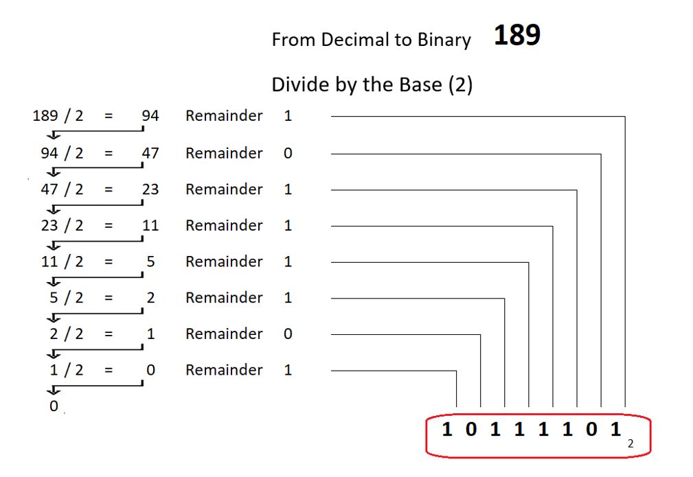
To convert from decimal to binary, divide the decimal value by 2. Make note of the quotient and jot down the remainder as the least significant digit of the converted number.
Now take the quotient from the previous division and divide it by 2. Make note of this result and jot down the remainder as the next most significant digit of the converted number.
Repeat this process until the resulting quotient is 0 and you should have the converted value written down.
Octal System
Base 8. Some older PLCs use octal numbering to represent addresses.
The digits in this system are 0, 1, 2, 3, 4, 5, 6, 7


To convert from decimal to octal, divide the decimal value by 8. Make note of the quotient and jot down the remainder as the least significant digit of the converted number.
Now take the quotient from the previous division and divide it by 8. Make note of this result and jot down the remainder as the next most significant digit of the converted number.
Repeat this process until the resulting quotient is 0 and you should have the converted value written down.

Hexidecimal System
Base 16. Many PLCs and connected devices display error codes in hexadecimal
The digits in this system are 0, 1, 2, 3, 4, 5, 6, 7, 8, 9, A, B, C, D, E, F


To convert from decimal to hexadecimal, divide the decimal value by 16. Make note of the quotient and jot down the remainder as the least significant digit of the converted number.
Now take the quotient from the previous division and divide it by 16. Make note of this result and jot down the remainder as the next most significant digit of the converted number.
Repeat this process until the resulting quotient is 0 and you should have the converted value written down.

The Easy Way
Converting the base of a number can be easy, using Windows Calculator in Programmer mode.

Binary Coded Decimal (BCD) System
Binary Coded Decimal is different from the positional numbering systems we have looked at so far.
BCD is designed to interact with field devices, known as thumb switches and 7-segment displays, to input and display decimal numbers using a binary code

When the decimal numbers 0 to 9 are converted to binary, values up to 9 can be stored as 4 binary digits otherwise known as bits. 4 bits can actually store higher values, up to 15 (Binary 1111 = Decimal 15), but BCD only requires 0 through 9.

For BCD, bits are arranged in groups of 4. A group of 4 bits is known as a nibble. Each decimal digit is handled as a separate nibble and its value stored in 4 bit binary.


Numeric Data Types
Sizing of Data Units
The smallest unit of data is a bit. Bits can be in one of two states. 1 or 0. Bits are regularly grouped together into segments of different sizes depending on the job they do. Some of the common data unit sizes are listed.
- Bit, short for Binary Digit is the smallest most fundamental unit of data.
- Nibble, made up of 4 bits.
- Byte , made up of 8 bits
- Word, made up of 16 bits
- Double Word, made up of 32 bits

Basic Data Types
A data type will make use of different sized data units. Numbers can be expressed in different formats with a varying range of values depending on what data type is used. The basic data types, sometime called the atomic data types, are simple data types consisting of one piece of data. The basic data types include boolean, integer and floating point. When programming PLCs, if performing mathematical operations or moving data, it is important to select a suitable data type or else the output could be corrupted. Consideration should be given to the range of numbers, does that range extend into negative values and are floating points required.
Data types are defined by the PLC manufacturer and made available to the PLC programmer. The data types that are already part of the package are known as Predefined. Exactly what data types are predefined will differ depending on the manufacturer.
Boolean
The Boolean data type is a single bit that represents two possible states.
1 = ON and 0 = Off
or expressed as
1=TRUE and 0=False
Unsigned Integers
Unsigned integers are whole numbers, there is no floating decimal point. Unsigned integers are capable of handling positive whole numbers only.
Integer, 16 Bit Unsigned
This data type occupies 16 bits. Converting from binary, we can see, 16 bits could range from a value of 0 (all bits off) to a decimal value of 65535 (all bits on).

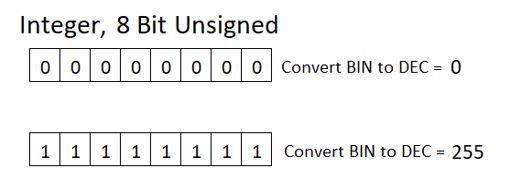
Integer, 8 Bit Unsigned
Like the above but occupying 8 bits. Range is 0 to 255.
Signed Integers
Remember, Integers have no floating decimal point. Signed integers are capable of handling positive and negative numbers.
Integer, 16 Bit Signed
This data type occupies 16 bits. Directly converting from binary, 16 bits could range from a value of 0 (all bits off) to a decimal value of 65,535 (all bits on). But signed integers need to express negative values as well. The bit that is most to the left is considered the most significant bit (MSB). The integer data type uses the MSB for a special purpose. The MSB is assigned a value of -32768 if the bit is set to 1. This gives the format the capability to express negative numbers.
Consider the diagram labelled Integer, 16 Bit Signed below. The word at the top of the diagram has 1s in the 15 bits to the right. This converts to a decimal value of 32767. We know the single word integer can represent a number as high as 32767.
The word in the middle of the diagram has all 16 bits set to 1s. We know the MSB has a special purpose and is worth -32768. So, add the first 15 bits worth 32767 to -32768 and the result is -1.
The word at the bottom of the diagram has the MSB set to one and the 15 bits to the right set to 0. The result is -32768. We know that the single word integer can represent a number as low as -32768.
If the MSB is 1 then we know the value will be a negative number.

Integer, 8 Bit Signed
The data type is 8 bits long. Like the signed 16 bit integer but with fewer bits. The MSB is assigned a value of -128 if the bit is set to 1. The range that can be expressed is -128 to 127

Integer, 32 Bit Signed
The data type is 32 bits long. Some PLCs combine two 16 bit words to create the data type. PLCs with 32 bit data buses use one word. Similar to 16 bit signed integers but with more bits to handle a much larger range of values. The MSB is assigned a value of -2147483648 if the bit is set to 1. The range that can be expressed is -2147483648 to 2147483647.

Floating Point
Single Precision Floating Point
The floating point data type can store numbers with decimal places. It occupies 32 bits. The format is standardized as IEEE 754. To manage a wide range of numbers with decimal places, the 32 bit structure is divided into subgroups. The subgroups hold different attributes that encode the stored number. The following is a brief description of the structure of the data type. For full details, the standard IEEE 7854 should be consulted.
The MSB will represent the sign of the number, 0 if positive and 1 if negative.
8 bits are assigned to hold an exponent value. The exponent is used in a method like scientific notation but base 2 is used instead of base 10. 2 to the power of the stored exponent represents the magnitude of the number. The exponent value has a bias value of 127 added.
23 bits are assigned to hold a fractional component of the number know as the Mantissa. The Mantissa added to 1 and then multiplied by 2 to the power of the exponent will decode the stored number.

Double Precision Floating Point
For greater accuracy on a wider range of numbers with decimal places, some PLCs have double precision floating point available. It occupies 64 bits. The concept is like the single precision floating point and it belongs to the same standard IEEE 754. Larger groups are assigned for exponent and fractional data.
The MSB will represent the sign of the number, 0 if positive and 1 if negative.
11 bits are assigned to hold an exponent value. The exponent value has a bias value of 1023 added.
52 bits are assigned to hold a fractional component of the number know as the Mantissa.

Other Data Types
When programming the PLC you will become aware of other more sophisticated data types. Different members of the basic data types are grouped together into predefined types that support PLC operations. There are predefined data types for timers, counters, math operations and file control operations just to name a few.
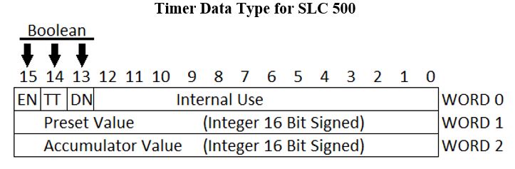
Consider the diagram Timer Data Type for SLC 500. It is made up of three 16 bit words. Bits 13, 14 and 15 of Word 0 are boolean data type. The booleans are to express the on/off state for the timer Enable, Timer-Timing and Done. Word 1 and Word 2 are singed 16 bit integers containing numeric data for the timer preset and accumulator.
Timer Data Type For SLC 500
Some PLCs have a feature that permits the programmer to create custom, user defined, data types. User defined data types would be made up by using existing data types as building blocks and grouping them together.
Boolean Logic
Every programmer needs to grasp the logical concepts of AND, OR and NOT to program a PLC. It serves as a solid foundation for all PLC languages. Electrical elementary ladder diagrams can help us illustrate the logical concepts AND, OR, and NOT. Electrical circuits have contacts that control electric current through the circuit, but we can start to think of electrical continuity and logical continuity at the same time.
AND Operator
Electrical elementary ladder diagrams can help us illustrate the logical concepts AND, OR, and NOT.
Consider the diagram titled Two Pushbuttons In AND Arrangement. The diagram shows a circuit with push buttons A and B in series. If button A and button B are pressed then lamp C will light. We can say the pushbuttons in series have an AND relationship.

Boolean algebra is a means to analyze logic and is a good way to express logic as equations made up of AND, OR and NOT operators. Some guidelines for Boolean algebra as applied in this lesson are:

Based on these guidelines we can write the Boolean equation for the diagram titled Two Pushbuttons In AND Arrangement that looks like this:

If we apply all possible variables to A & B we can create a truth table for the basic AND relationship.

OR Operator
The diagram titled Two Pushbuttons In OR Arrangement. Is an electrical elementary ladder diagram that shows a circuit with pushbuttons A and B in parallel. If button A or button B are pressed then lamp C will light. We can say the pushbuttons in parallel have an OR relationship.

The Boolean equation for the diagram titled Two Pushbuttons In OR Arrangement is:

If we apply all possible variables to A & B we can create a truth table for the basic OR relationship.

The AND OR operators can be combined to create more complex ladders. The diagram titled Pushbuttons In Combined AND OR Arrangement. Is an example.


NOT Operator
The NOT operator inverts the value of the variable.
For example:

The diagram titled Pushbutton In NOT Arrangement. Is an electrical diagram with a normally closed type pushbutton, called A, and a lamp C. It is a circuit where, if button A is not pressed then lamp C is lit. When button A is pressed then lamp C will go out.

The Boolean equation for the diagram titled Pushbutton In NOT Arrangement is:

With this equation we can create a truth table for the basic NOT relationship.

The NOT operator can be combined with the AND & OR operators.


All operators can be combined to make more complex ladders.

Thank you for reading the learning series, PLC Part 1 Fundamentals.
Click on this link to proceed to the next section PLC Part 2 Intro To CODESYS.
References – Books And Weblinks
You can explore more on the subjects discussed in PLC Part 1 Fundamentals with these books and links.
Conventional Current Flow – Book – Eugene Lister and Michael Golding, Electric Circuits and Machines, 1st Canadian Edition. (Toronto: McGraw-Hill, 1987), 4.
PLC Hardware, numbering systems and boolean logic – Book – Richard A Cox, Technician’s Guide to Programable Controllers, 3rd ed. (Albany: Delmar, 1995).
Electronics, BCD – Book – Terry Bartelt, Industrial Automated Systems: Instrumentation and Motion Control. (Clifton Park, NY: Delmar/Cengage Learning, 2011).
Allen Bradley I/O modules – Technical Manual or Report – Rockwell Automation, 1756 ControlLogix I/O Modules Specifications, Publication 1756-TD002N-EN-E, (Milwaukee: Rockwell Automation, Nov. 2021),
Floating Point Data Type – Blog Post / Web Article – S.Orley and J. Mathews. ”The IEEE 754 Format” Emory Oxford College The Department of Mathematics and Computer Science, http://mathcenter.oxford.emory.edu/site/cs170/ieee754/
PLC History – Blog Post / Web Article – Chris Vavra. ”Dick Morley Remembered as Father of the PLC” Control Engineering, 2017 https://www.controleng.com/articles/dick-morley-remembered-as-father-of-the-plc/https://www.controleng.com/articles/dick-morley-remembered-as-father-of-the-plc/
PLC Memory – Blog Post / Web Article – Viral Nagda. ”Types of PLC Memory” Instrumentation Tools, https://instrumentationtools.com/types-of-plc-memory/